
Mishimoto Compact Baffled Oil Catch Can, Part 2: Prototype Development and Testing
Interested in purchasing this catch can? Check out our product page for more information!
Mishimoto Compact Baffled Oil Catch Can
Time to fabricate/prototype our awesome catch can design! We would be using our in-house fabrication equipment and our 3D printer to develop a plastic and metal prototype.
Prototype Fabrication
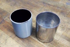
We began by fabricating the base of the can from aluminum. Dan set to work cutting, welding, and polishing the base you see below.
Fabricated base for new oil catch can
Notice that the base of this can does not feature a drain. We did not incorporate one into our initial fabricated component, but we do plan to add a drain port on the base for those who wish to install a valve or drain line to the oil pan. No details were left untouched during development.
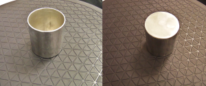
Next, we printed a unit and coated the inside for testing. The 3D printed material is somewhat porous. We use an internal coating that properly seals the components and provides a surface with properties similar to our final product.
Fabricated catch can base (right) and 3D-printed base (left)
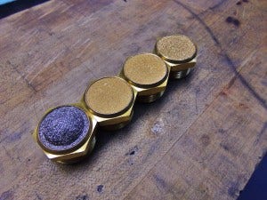
Next up was the baffle unit. We constructed a few metal prototypes as well as a printed version of our planned baffle design. Notice below that the fabricated units on the left differ slightly. They are primarily for basic mockup, so for this testing we did not need to drill all the holes that would be in the final product.
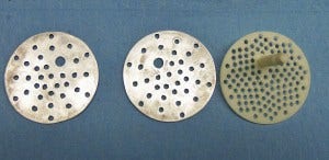
Fabricated catch can baffles (left, center) and 3D-printed baffle
As mentioned in Part 1 of this blog, this baffle will promote oil vapor condensation, enhance the separation of contaminants, and prevent collected oil from splashing about in the can.
Our next targeted component was the top of the catch can. This would house the ports for air entry/exit, enclose the filter and diverter, and would have provisions for the mounting bracket.
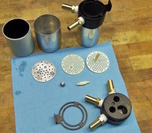
Fabricated catch can components
We chose to 3D-print this top and mounting bracket, and in the meantime we worked toward getting some CNC-machined prototypes constructed. For now, the 3D units would function for our needs and provided a basic glimpse of what this catch can would look like. Don't worry, we will not be including brass fittings in the final product; these are being used as a representation of the components we will later design. The small white rod attaches the baffle to the lid. The rod is removable, making this catch can very user friendly and serviceable.
Also notice the prototype mounting bracket (bottom left) we printed in 3D. This unit features three slots that pivot around the lid of the catch can. This means you can turn the can nearly 360 degrees, which is a huge advantage when you are situating your inlet/outlet locations. A stationary bracket would limit mounting options, and we found that this pivoting design is very strong and extremely versatile.
Check out the upper portion of this can fully assembled!
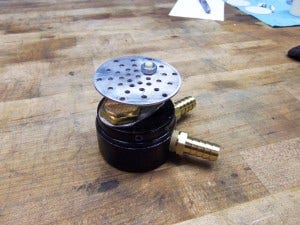
Assembled top of prototype catch can
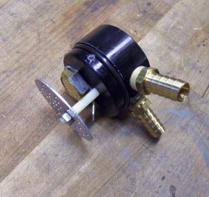
Assembled top of prototype catch can
One component has yet to be discussed, the small silver diverter that is mounted around the filter. Our goal with this component is to increase turbulence within the can to promote greater separation. CFD testing has shown that this simple addition makes a significant impact on air turbulation, which will help our product perform even better.
Now that we had a basic functioning representation of what our catch can would look like, it was time to test the functionality. We prepared a simple bench test that would generate similar conditions to what you would see with a common CCV system. Dan fabricated some mounting devices for the testing components, shown below.
Catch can test-rig assembly
A few quick bends!
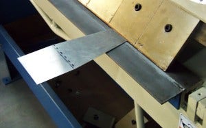
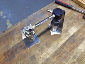
Catch can test-rig assembly
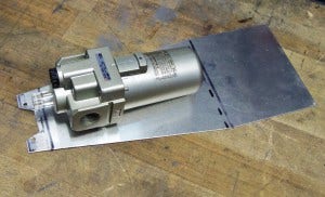
Add a few mounting holes and we now have mounts for both the catch can and the pneumatic lubricator. This device (commonly used to oil air tools) will allow us to adjust the oil droplet rate and will atomize the fluid for entry into our catch can. This is an accurate way of introducing a stream of oil vapors/fluids into the can so we can test for separation.
Catch can test-rig assembly
The purpose of this procedure was to test several different filters so we could evaluate their performance and efficiency for separating air and oil. Check out our filter options!
Catch can filter evaluation
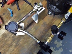
With everything prepared, we set up the testing device in two ways. First, we pressurized air before entering the catch can, pushing it through the pneumatic lubricator and then through the catch can. We then looked for the presence of any oil in both the can and the contents of the air passing through the can.

Setup 1 for catch can testing
If you look closely at the image above, you can see the oil building up before entering the catch can. Notice also that the line exiting the can does not have any sign of residue or fluids.
For our second test, we used a venturi tee to create a vacuum-like effect on the catch can and oil. Take a look at the shot below!
Setup 2 for catch can testing
For this setup, air passes through the tee and out to the right. This creates a vacuum effect on the line going to both the catch can and the pneumatic lubricator. This vacuum pulls the air/fluid through the can instead of pushing it, similar to the function of a portion of your CCV system. As with the first setup, oil is present before entry to the can, while the hose exiting the can is completely oil free. Using these two testing setups we were able to evaluate the effectiveness of the filters shown above, eventually settling on the 50 micron bronze filter. Check out a quick video displaying the filter testing.
Now that we had all of the details sorted out, we CNC-machined a final prototype for our concluding evaluation. Check back next time for a look at this final prototype!