ReSpiration Focal Point - Intake R&D, Part 2: Something's Rustling Up
The RS has gotten a lot of attention the past few weeks, especially with the ball in our court. Need I remind you of our awesome stock dyno clip?
But somethin's-a-brewin with one of our most recent projects, the performance intake we are developing for this hot hatch. We mentioned earlier that the development of this intake kit is not completely uncharted territory, considering that we made one for the 2013-2014 Focus ST. However, as we dived further into this project, we uncovered the true complexities of this design compared with our ST intake kit.
Intake Construction
What exactly makes this intake pipe so much more complex? It's simple: More attachments and brackets need to be added so that the fit will be accurate. Not only have the number of these attachments increased, but also the orientation of these pieces are not easy to accommodate. There will be bends with relatively tight tolerances, and these measurements must be exact. Difficult? Yes. Impossible? Not at all!
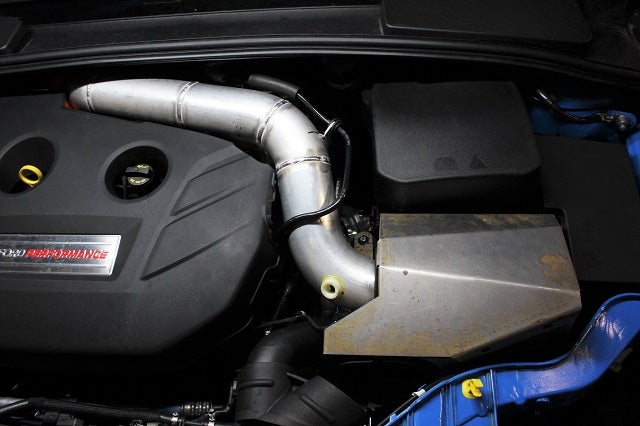
First, we needed to decide how the pipe should be routed around the engine bay with all the attachments and brackets properly placed. Almost immediately, we knew we'd want to use a silicone piece that attaches to the turbo behind the motor, but for the mockup, this part was printed.
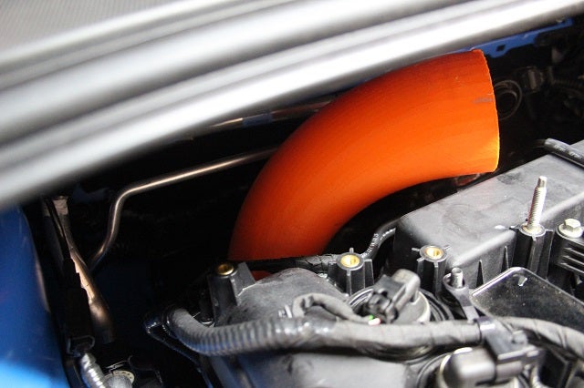
3D printed turbo elbow for the Ford Focus RS performance intake prototype
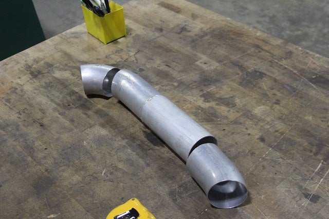
Initial pipe design ready to be fully welded together
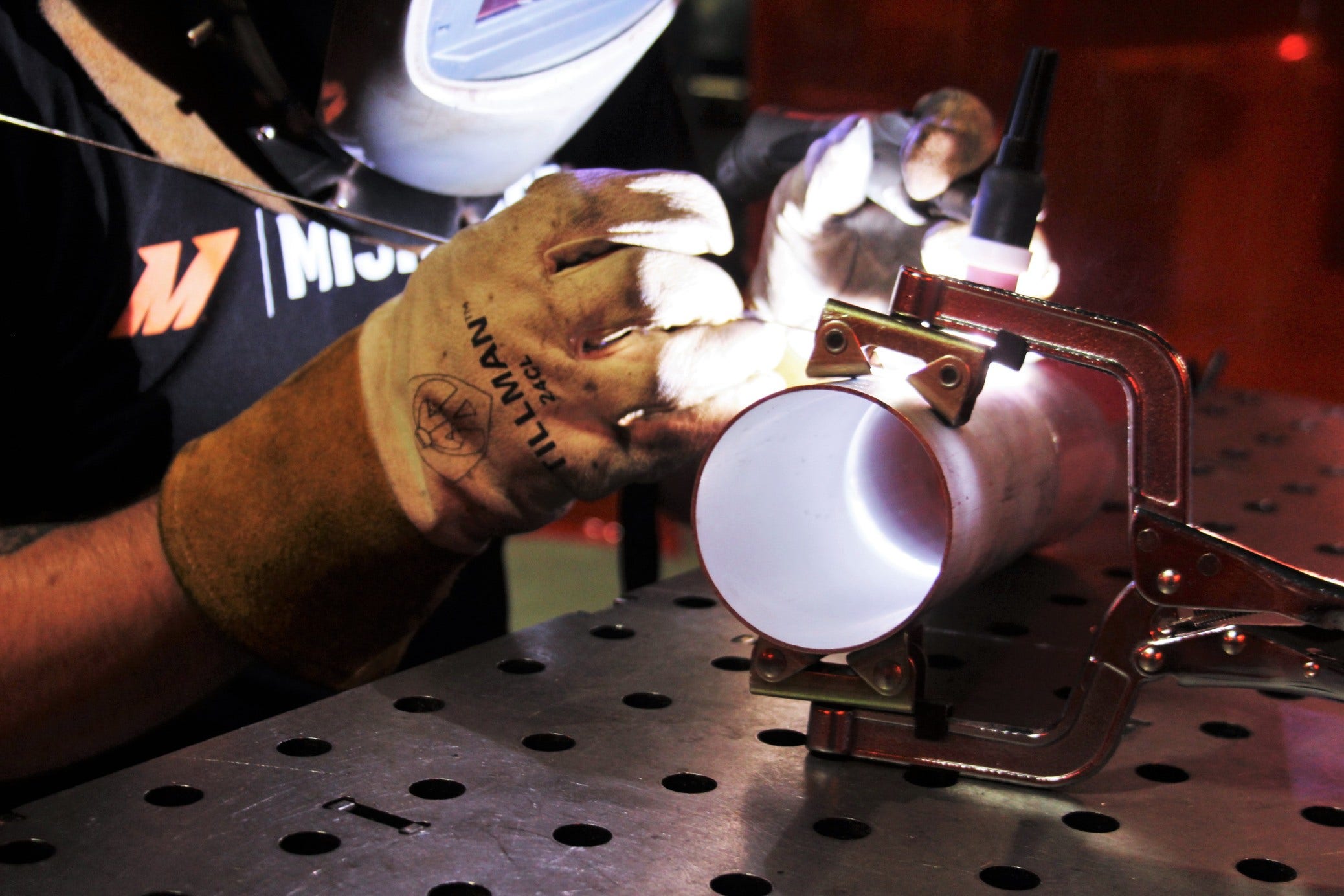
Now it comes down to the long piping section. Once the initial mockup of the piping was completed, it was up to our lead fabricator, Mike, to get the pipe welded together and mocked up on the car.
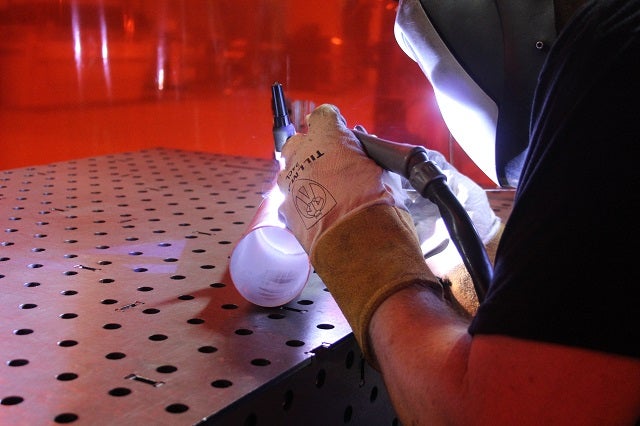
Check out Mike working his magic!
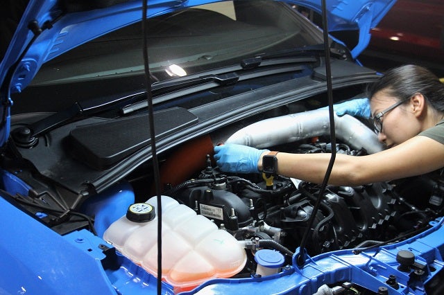
Our engineer, Ye, confirming the successful fitment!
Once this step was completed, it was time to make those brackets and attachments that would hold the intake pipe properly in place. This part of the project is actually very interesting because of how we developed these small components using our waterjet. Check out a shot of it in action below!
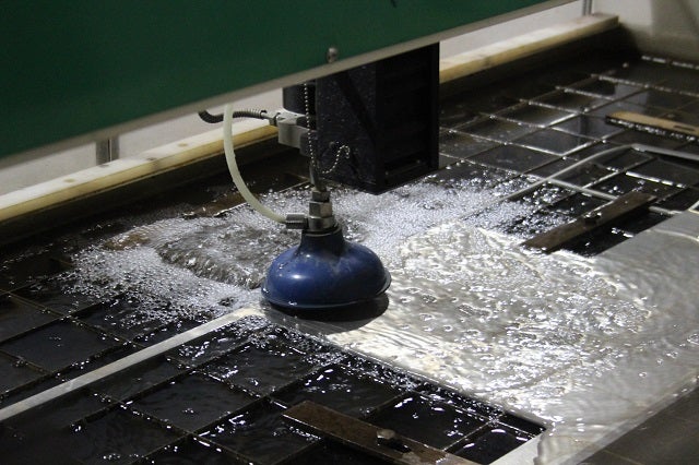
The waterjet, jetting away
When the water settles, you get the resulting cutouts.
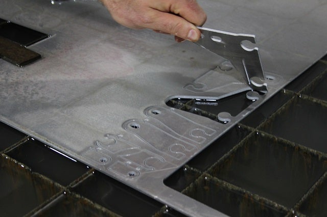
Pick-a-part"literally!
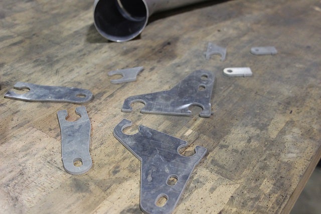
All attachments and brackets laid out
This process is cool because it shaves off time from the R&D process. Before our waterjet days, these particularly small yet complex pieces would have been painstakingly cut by using a myriad of different drill bits, tools, files, etc. With no waterjet, this part of the project would have taken about five hours to complete. Now, however, we upload the exact specs of these pieces to the waterjet computer, and it simply cuts them using high-pressure water mixed with an abrasive material. Total time taken? About 30 minutes - the longest part of that being the machine setup, which generally takes around 25 minutes. Time is money, so, yeah, we'll take the latter.
In the images below, the parts have been properly bent to their correct shapes. Take a look at the fitment.
Bracket with 3D printed pipe adapter
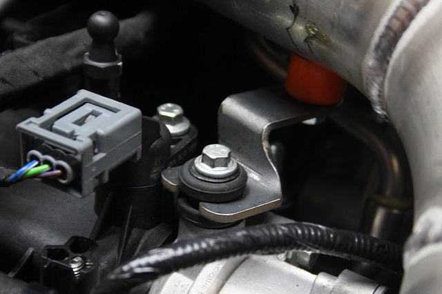
Bracket with 3D printed pipe adapter
Attachment holding a line
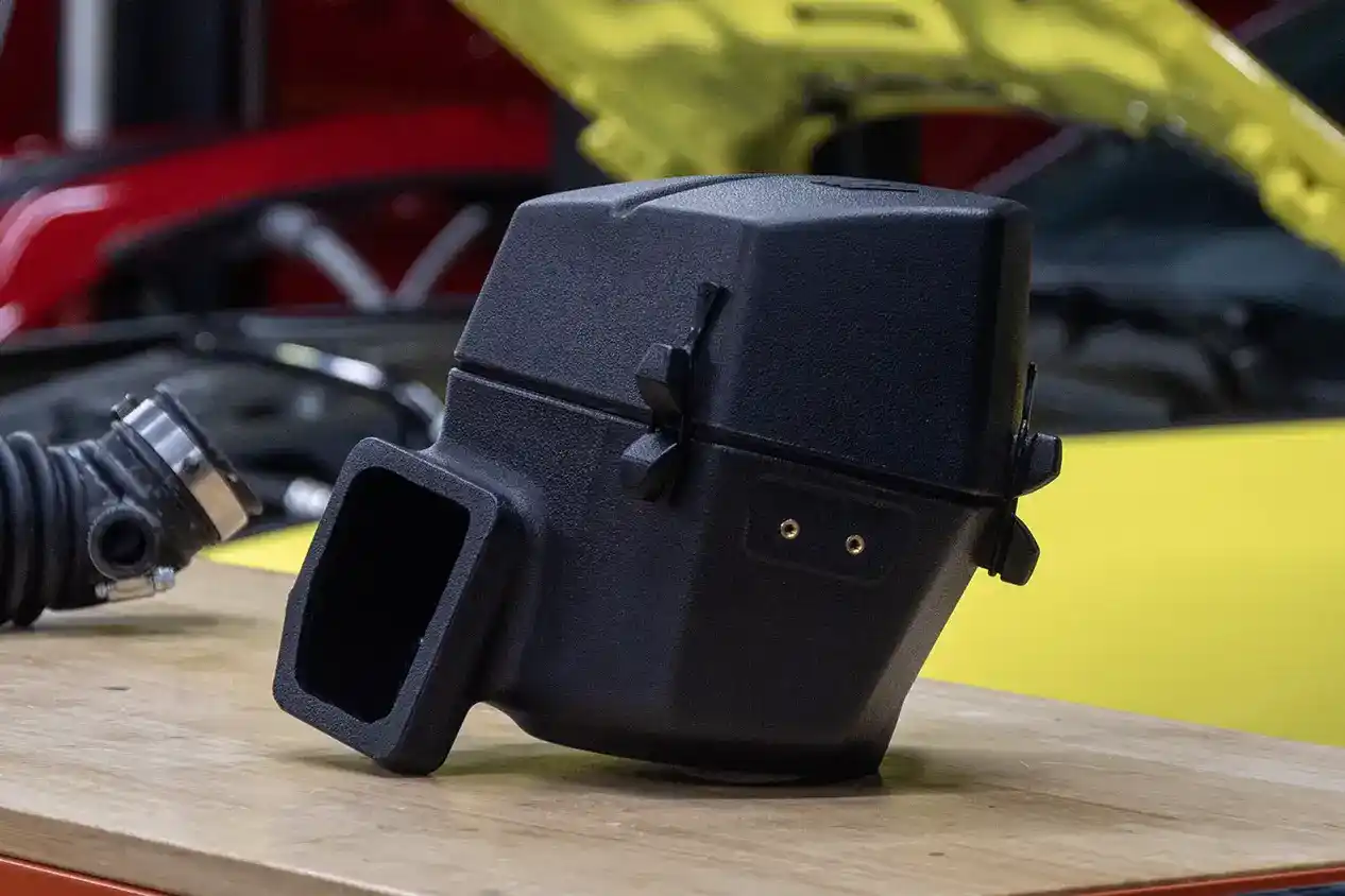
Next up was the airbox, which is pretty similar to the ST box, but Ford made a statement with its honeycomb lid design. It is certainly one of the more visually pleasing stock intake airboxes we have seen here at our R&D facility. Getting air to the filter is important, so we will be using both of the fresh air inlet scoops that route into the stock airbox with the OEM-supplied inlet tubes.
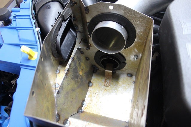
Airbox prototype
One difference is the lid; our ST lid is completely flat
These airboxes appear to be somewhat similar, but they are actually very different with minor, yet significant dimension disparities in the digital 3D design space. One immediately noticeable difference is the prototype airbox lid; the ST lid is completely flat, whereas our RS lid has some bends that create a bit of a curve.
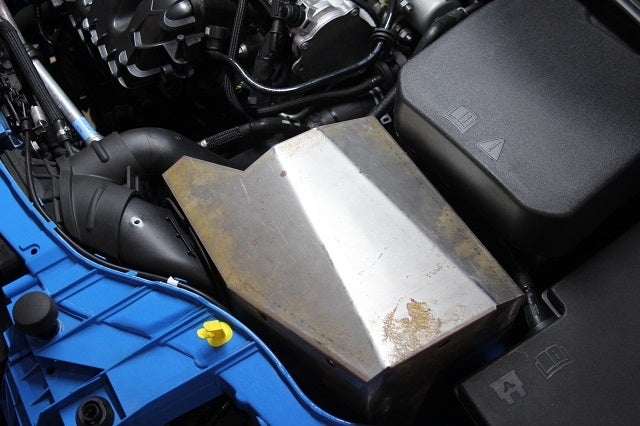
So what does the entire prototype now look like? See for yourself!
What a prototype!
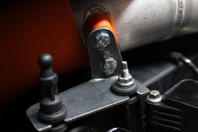
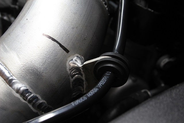
Above, you can also see one last addition, which is the fitting for the IAT sensor. It has been glued on for now using a highly adhesive epoxy. This prototype is not a particularly good looker right now, but that's all part of the R&D process! Next up, dyno time - let's see if we can get a tune out of this trombone!
Thanks for reading.
-Diamaan