Drop Intake Temperatures. Drop Track Times. Drop Jaws. The Ultimate Guide For Intercooler Selection!
What intercooler should I get? Is this a good intercooler? What horsepower gains will I see with this intercooler? Is a universal intercooler right for me? We all see these questions on Internet message boards, and we even hear them in friendly discussions with fellow car folk. Instead of responding with a face palm, we need your help to educate the masses on how an intercooler works. Knowing what makes a great intercooler great is powerful knowledge that can help you select the best cooler for your project.
The goal of this article is to explain intercooler systems, designs, features, and testing procedures, so that you can more easily select the intercooler that meets your needs. Don’t be that guy with a massive front-mount intercooler on a completely bone-stock vehicle complaining about boost lag. Check out the guide below to educate yourself, your friends, relatives, maybe even that guy at work claiming his three-fifty will blow the doors off your measly 4-banger. With our help here at Mishimoto we will make sure when you are looking to buy a Focus ST intercooler, that you actually find the right model intercooler to make your car better.
This article includes information from basic intercooler function to advanced discussion about core design and heat transfer. Feel free to utilize the table of contents below to skip around to sections that interest you.
Table Of Contents
1. Intercooler Function (CAC Basics)
A. Turbocharger
B. Piping and Boots
C. Intercooler
2. Intercooler Types
A. Liquid-to-Air
B. Air-to-Air
C. Which Should I Build?
3. Where's The Cooler?
A. Top-Mount (TMIC)
B. Side-Mount (SMIC)
C. Front-Mount (FMIC)
4. End-Tank Construction
A. Plastic
B. Stamped
C. Cut-and-Weld Aluminum
D. Cast Aluminum
5. Core Construction
A. Tube-and-Fin vs. Bar-and-Plate
B. Fin Styles
C. Fin Density
D. Optimal Airflow (Core Placement)
6. Inlet and Outlet Sizing
A. Staggered Inlet/Outlet Sizing
7. Core Volume and Surface Area
A. Intercooler Sizing Example
8. Surface Finish
A. Powder-Coated
B. Painted
C. Anodized
D. Durability
E. Heat Transfer
9. Maintenance
10. Leaks
11. Testing
A. Intake Temperatures and Efficiency
B. Pressure Drop
C. Power Output
12. Conclusion
1. Intercooler Function (CAC Basics)
We’re going to start this article with some basic knowledge needed to fully understand how a charge air cooler (CAC) system functions to improve the power of your vehicle. Let’s begin with a fun pop quiz. What were the first turbocharged production vehicles? Stop opening a new tab to google this … Unless you include commercial vehicles developed by the Swiss, the answer is GM’s 1962 Oldsmobile Jetfire and Chevrolet Corvair.
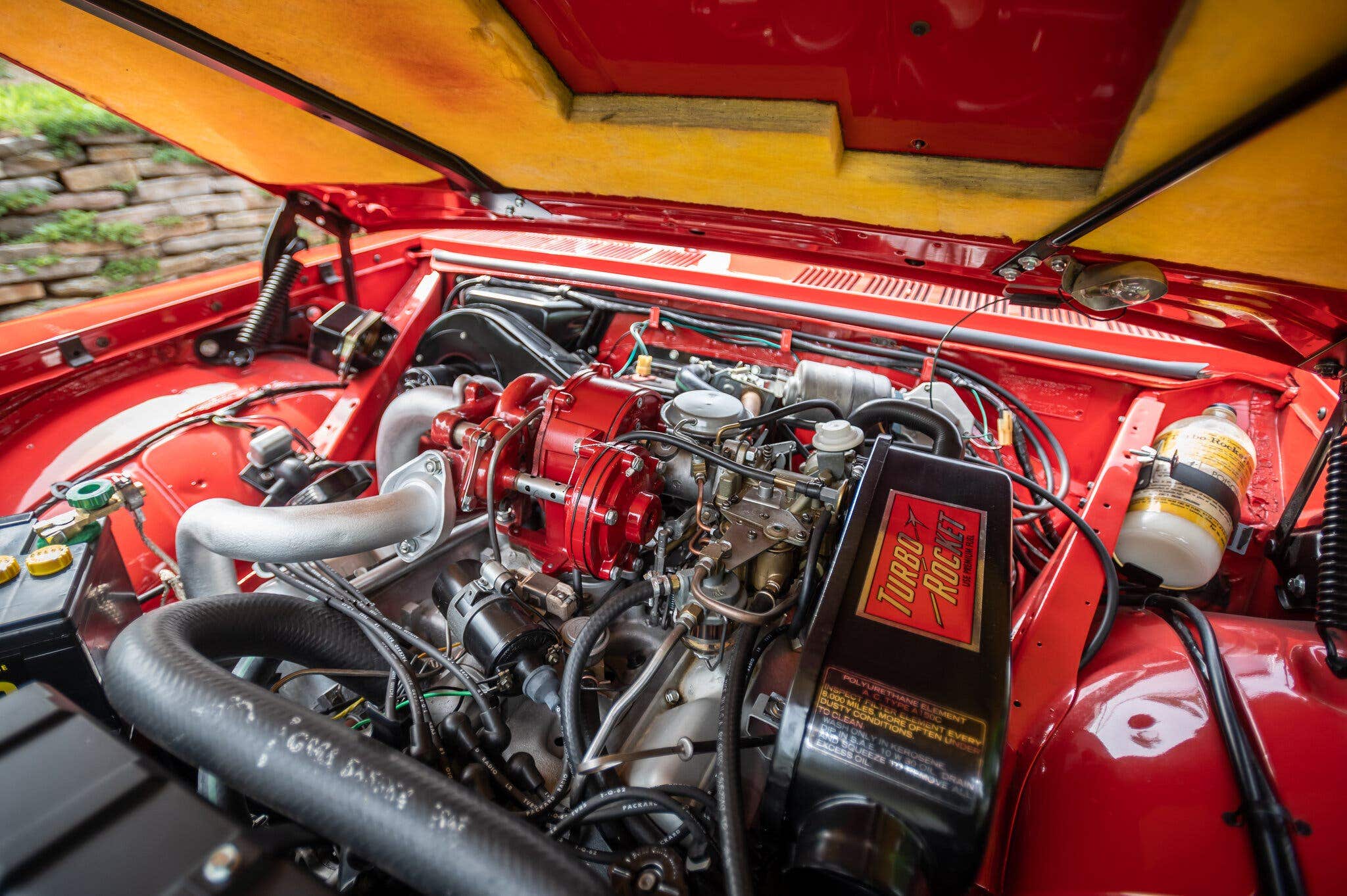
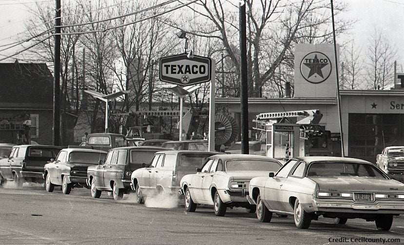
The point behind this question is that turbocharging technology has been around for quite some time, but the technology did not come into its own in production vehicles until the 1980s. We can thank the fuel crisis for the introduction and widespread use of turbochargers, whose purpose was to produce greater power without a significant impact on fuel economy. Such advances in automotive technology allowed manufacturers to turn lemons into lemonade, and they set the tone for several decades of successful turbocharger improvements and implementation.
Now, you can walk into just about any car dealership and spot a turbocharged model in seconds. So let’s look into how these systems function to improve power output while retaining fuel efficiency.
A. Turbocharger
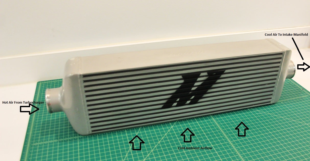
Before jumping into the actual intercooler kits, we need to see why a turbocharger is even necessary. A turbocharger is an interesting piece of machinery. In a nutshell, the turbo recycles the engine’s exhaust gases by compressing intake air before entering the engine. When this compressed air is forced into the cylinders to mix with the fuel, more power can be made. For readers who are visual learners, reference the image below.
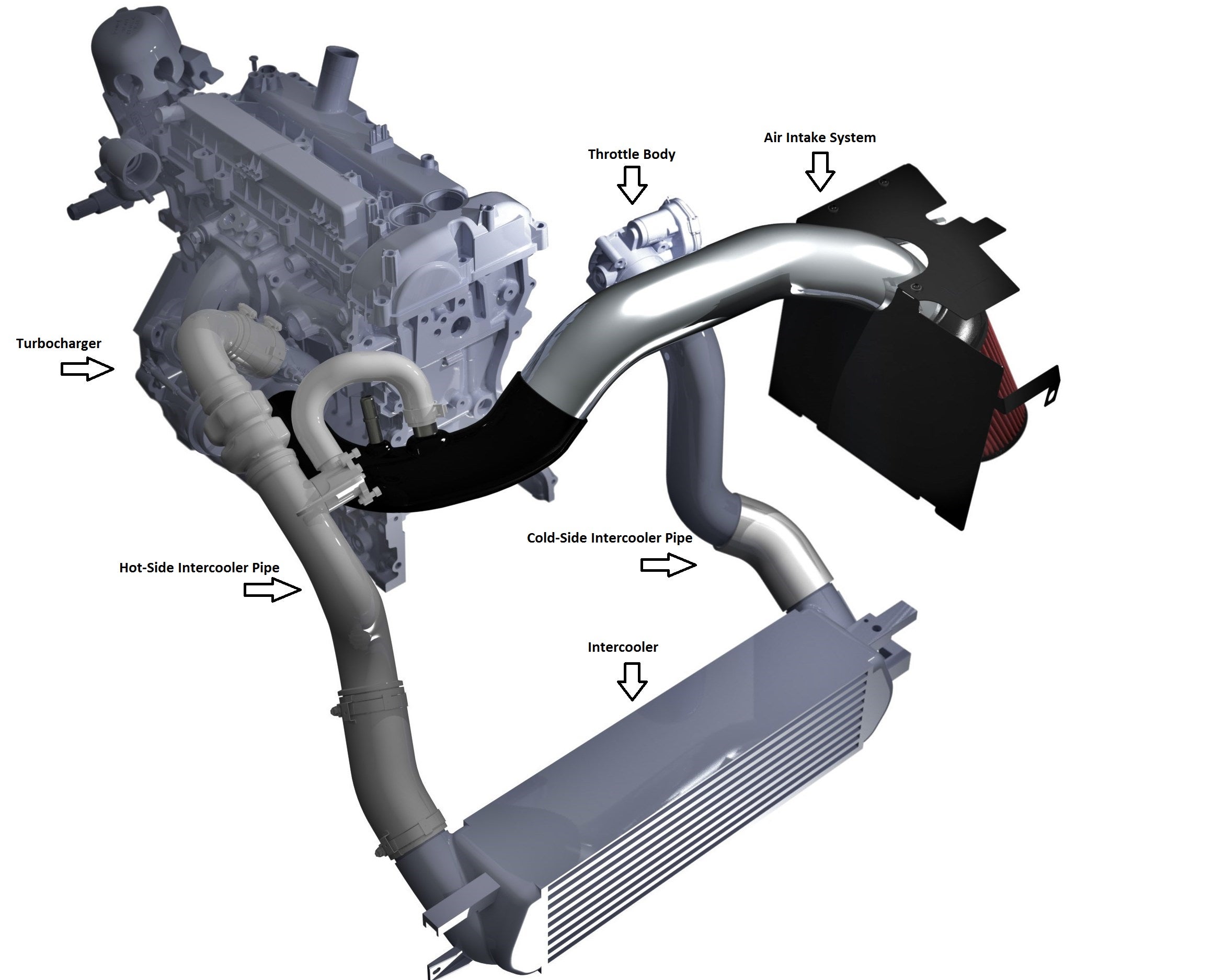
So as you see in this image (starting at the upper right), ambient air enters the turbocharger from the intake system, is compressed, and exits the housing heading toward the hot-side intercooler pipe.
Once through the intercooler, the now cold air passes through the cold-side intercooler pipe and into the throttle body (or intake manifold in vehicles without a throttle body).
Let’s discuss the internal portions of a turbocharger. An impeller is spun by the exhaust gases that enter the rear portion (exhaust housing) of the turbocharger. This impeller is connected to a shaft that runs the full length of the turbo to the compressor side. As the compressor spins, air is compressed, and the intake air enters the engine. Although it seems complex, the functionality is pretty basic: Compressed intake air pressurizes the intake system, resulting in a positive manifold pressure for producing more power.
If you prefer to keep things truly simple, this definition from the BBC’s Jeremy Clarkson is always a good bet: “Exhaust gases go into the turbocharger and spin it, witchcraft happens, and you go faster.”
B. Piping and Boots
Something needs to route air from your turbocharger to the other key components of the system. This is where intercooler piping and boots (couplers) come into play. Factory piping is typically constructed from steel or plastic, while aftermarket setups are usually made of aluminum. Either way, the piping will curve around the engine bay, going from the turbocharger, to the intercooler, then to the engine intake manifold. Couplers provide a connection point between these components while providing flex and serviceability of the individual pieces. We put together another article about piping and boot systems and how to put together a reliable system. For more information on that, check out the link below.
C. Intercooler
The almighty intercooler is a heat exchanger that transfers heat from one fluid to another. (Note: Engineers consider gases as “fluids,” because all principles and equations used to predict gases and fluids are identical.) In this case, hot air is entering the internal portion of the intercooler from the turbocharger. Although temperatures will vary based on the engine and turbocharger specs, we typically see inlet temperatures in the range of 225°F–275°F (107°C–135°C). As air passes through the external fins of the cooler, heat is transferred, resulting in a reduced temperature for air exiting the intercooler
So why would we want a colder temperature? As we all know, a combustion engine relies on a combination of air and fuel, ignited to produce our favorite tire-spinning activity. One key to producing optimal power is air density. The cooler the air, the more dense it is. Higher density will result in more oxygen content within the mixture, which allows for more fuel and a more efficient explosion that results in greater power. The goal for any vehicle is to reduce intake temperatures as close to ambient as possible. To do so on a turbocharged vehicle, a heat exchanger is absolutely needed.
Additionally, engine detonation (“knocking”) is far more common with high intake temperatures. Detonation occurs when a combustion process spontaneously takes place after normal combustion caused by the spark plug. This causes an instantaneous pressure spike within the combustion chamber. By reducing intake temperatures and improving combustion, we can reduce the chance of ignition detonation.
Detonation can be quite ugly and can result in overheating and severe engine damage. You want to avoid it like the plague. As long as you have a solid ECU tune and low intake temperatures, detonation should not be a concern.
So begins the journey to find the perfect intercooler for your street car, tire-shredding drag car, twin-turbo track rat, lemon budget build, AWD rally animal, twin-engine hill-climb monstrosity, or any other build or project you might have in the works.
2. Intercooler Types
There are basically two types of intercoolers: liquid-to-air and air-to-air. The decision between the two coolers is usually a matter of efficiency, power output, and vehicle use.
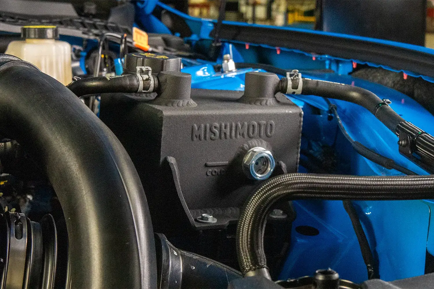
A. Liquid-to-Air
Just as the name implies, the liquid-to-air cooler uses engine coolant (typically on a secondary engine coolant circuit) to transfer heat from the air passing through it. The coolant and air are in different passages and do not make direct contact. This particular heat exchanger is extremely efficient and is actually finding its way into the engine bays of numerous OEM vehicles, including the 6.7L Powerstroke, the CLA45 AMG, and the BMW S55B30. I imagine this will be commonplace in the near future because of the improvements to its efficiency and component packaging.
In a liquid-to-air cooler, coolant is pumped through the channels and tubes that are attached to the fins in the heat exchanger. Air from the turbocharger flows through the fins, which allow for the transfer of heat between the air and coolant. A system such as this typically uses a low-temperature thermostat to regulate fluid temperatures.
Liquid-to-air systems are typically used for very high-powered vehicles that produce a great deal of heat. This system is more complex than a typical air-to-air intercooler, because it requires coolant lines, fittings, a coolant pump, and possibly an additional radiator, and it occupies a reasonably-sized footprint for the actual exchanger. Adding this type of complexity to the system is truly only worth the hassle for vehicles requiring substantial heat exchange. For most vehicles, a more typical air-to-air cooler is efficient enough for street and track use.
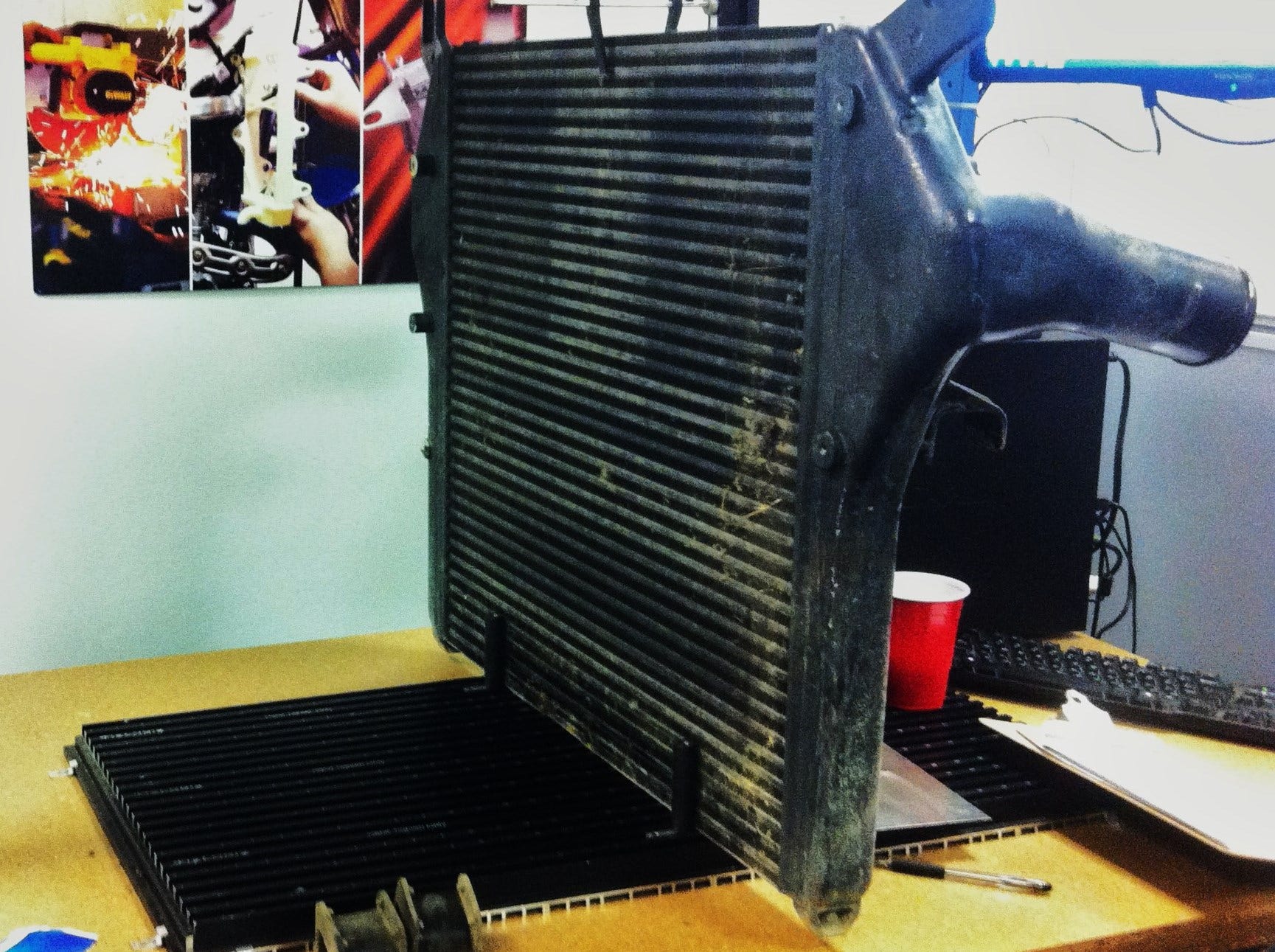
B. Air-to-Air
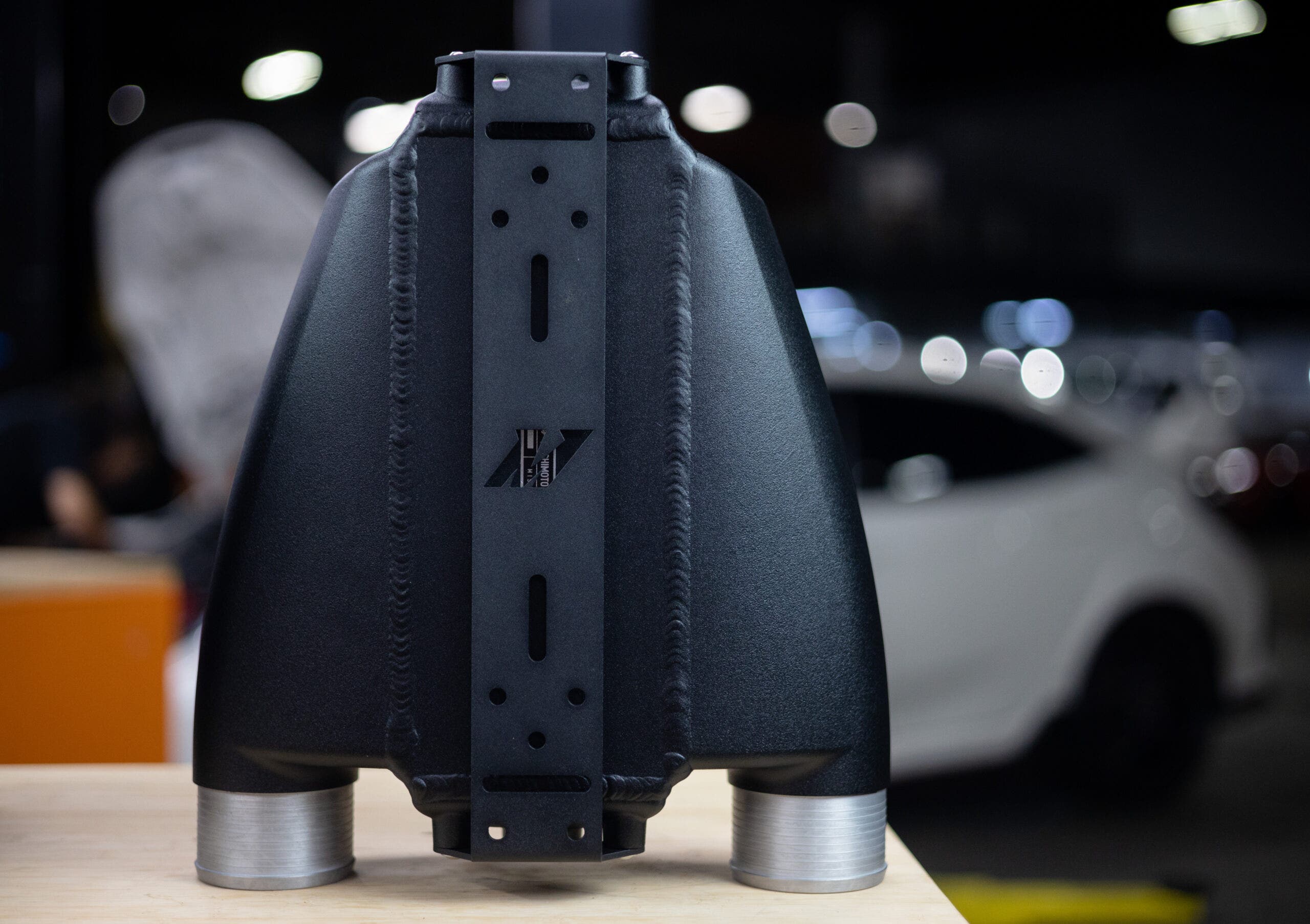
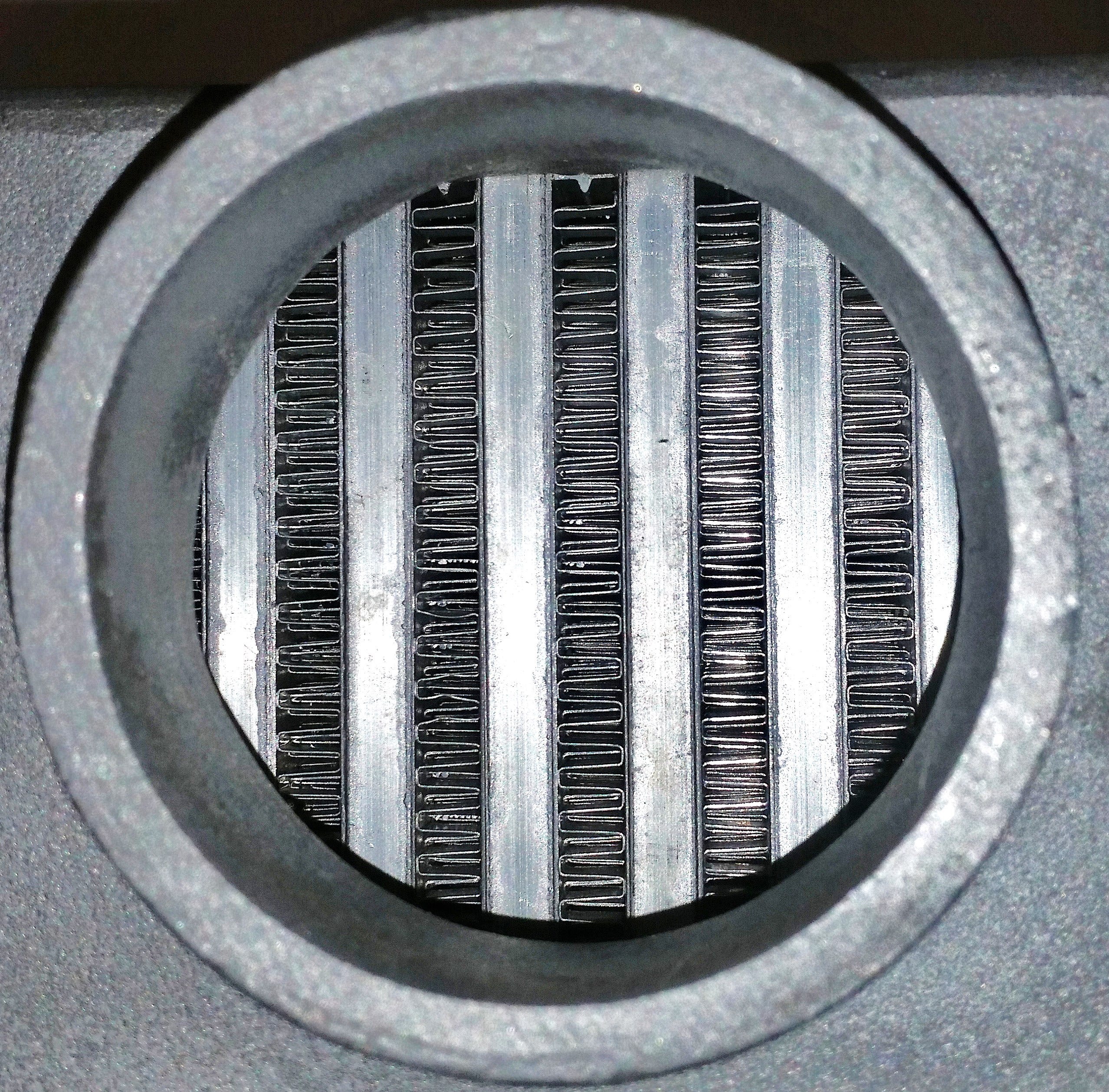
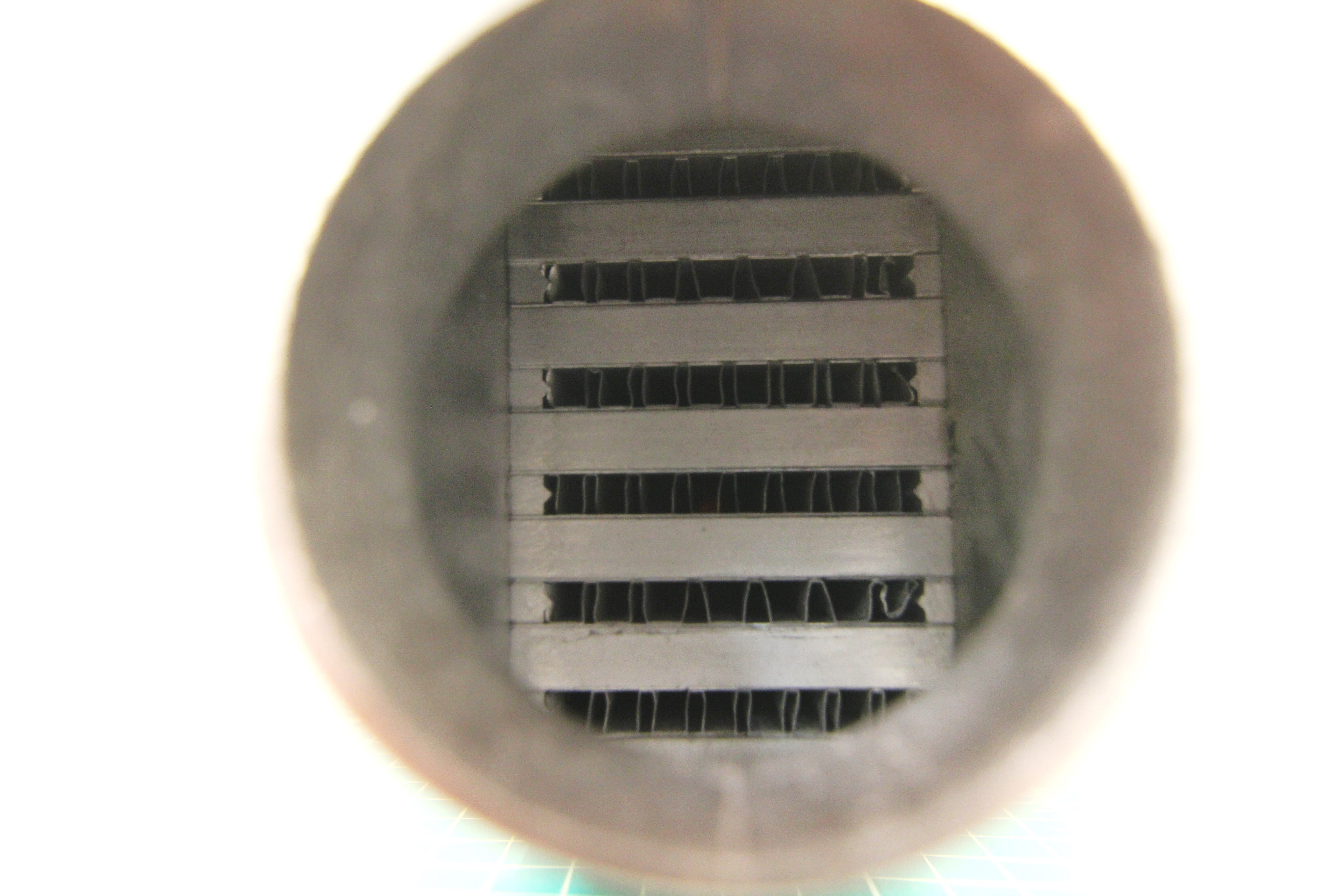
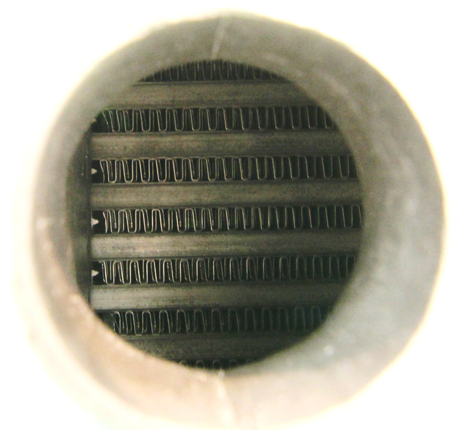
When someone speaks of an intercooler, the air-to-air more commonly comes to mind. This cooler will normally be visible from the exterior of the vehicle, such as when mounted within the front bumper. The reason for this is airflow. This cooler relies on airflow through the core for it to have an impact on CAC temperatures.
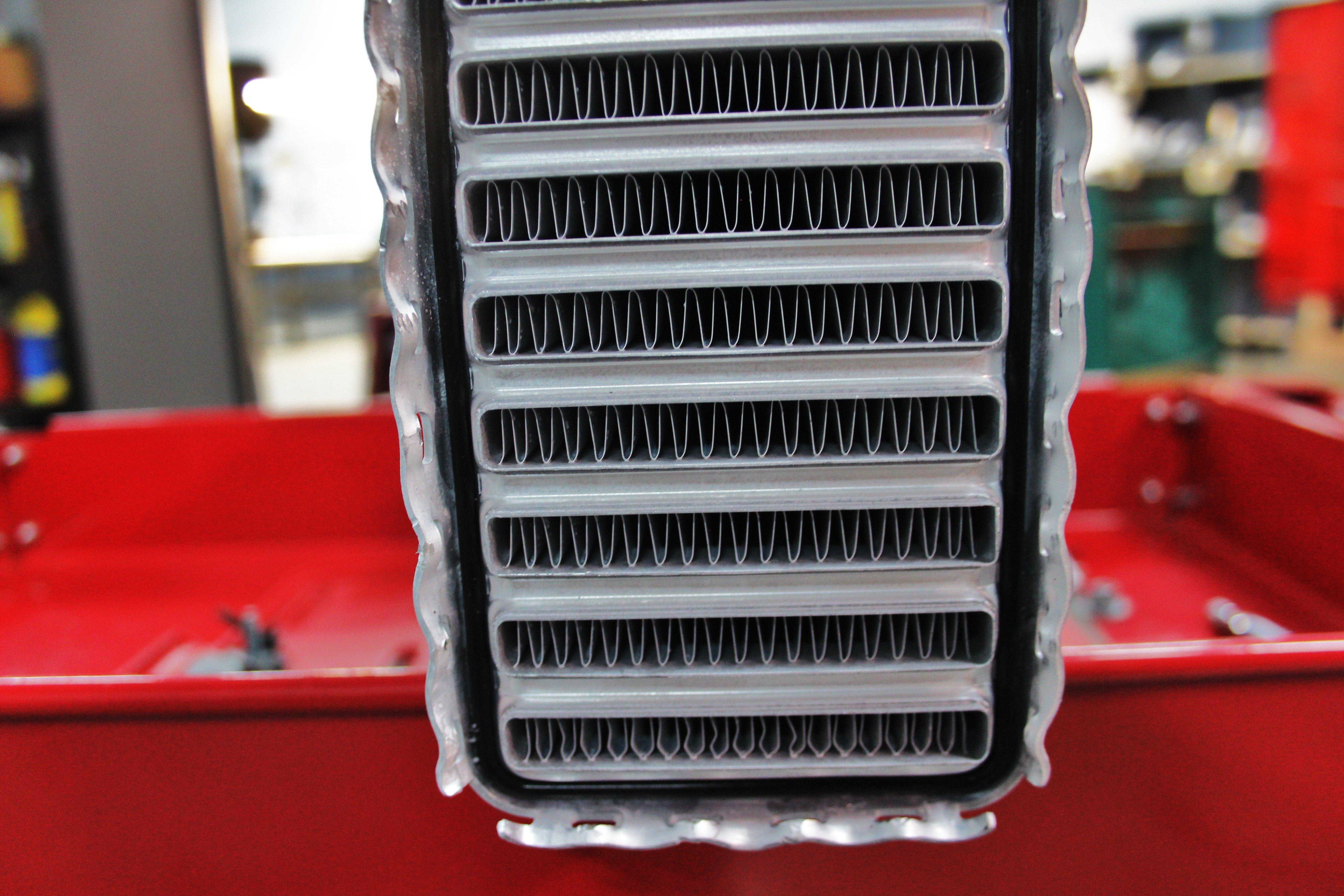
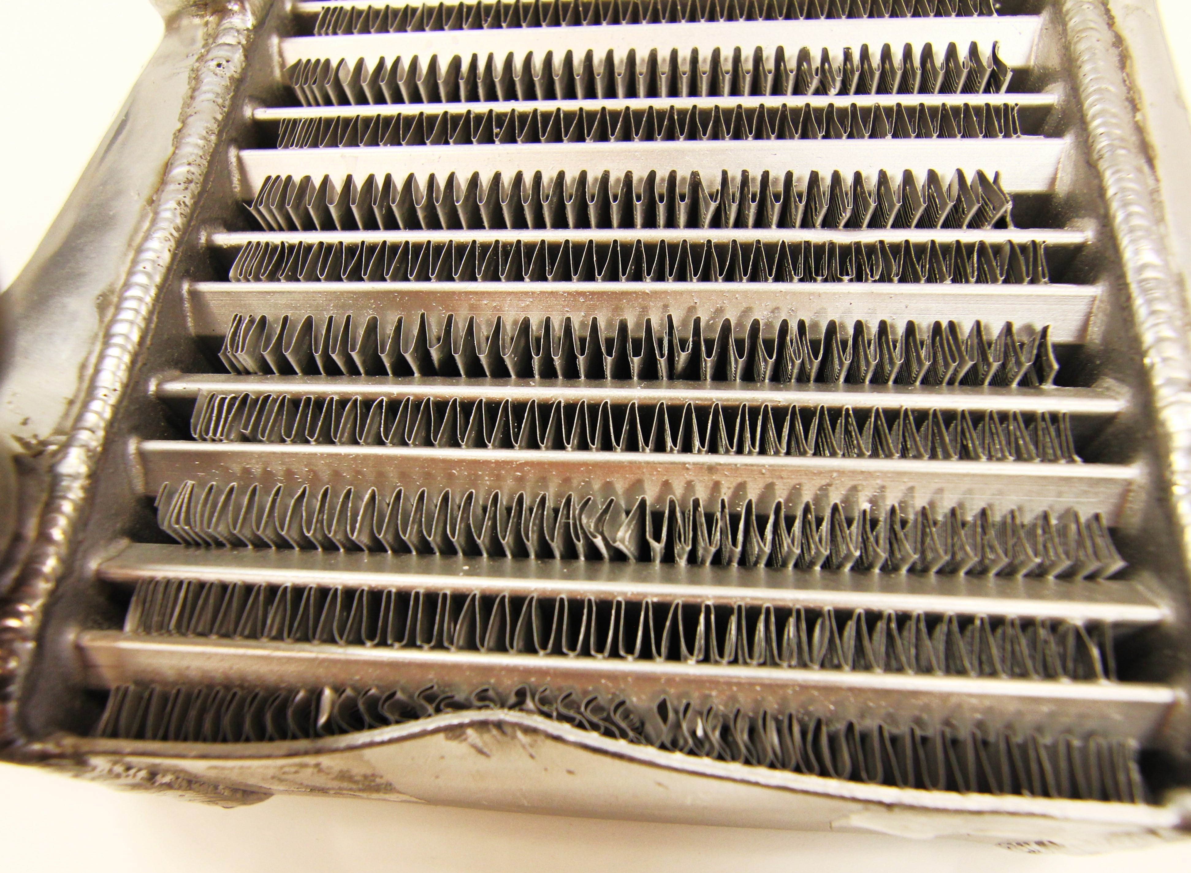
Referencing the image above, you can see the internal channels for airflow. This particular core is a bar-and-plate unit, which is discussed later on in this article in our Core Construction section. Air will pass through the channels of this cooler created by the bars and plates. On the outside of the cooler, finned rows are located between each bar. As air passes through these fins, heat is exchanged with the internal air, thus reducing temperatures.
An air-to-air system is very efficient; however, it does rely on airflow (from vehicle speed) to generate the needed cooling. At idle, these coolers can be prone to heat-soak when there is insufficient airflow. Although this is rarely an issue for front-mount setups, an air-to-air unit contained within an engine bay can certainly overheat at idle when engine bay temperatures begin to affect the cooler.
In general, this type of cooler is far more popular within the automotive world and offers the best monetary value in terms of cooling performance. For these reasons, the majority of this article will focus on air-to-air units and their features.
C. Which Should I Build?
Check out the pro/con chart below highlighting the benefits and downfalls of each system. This should help you weigh the options to go down the right route for your build.
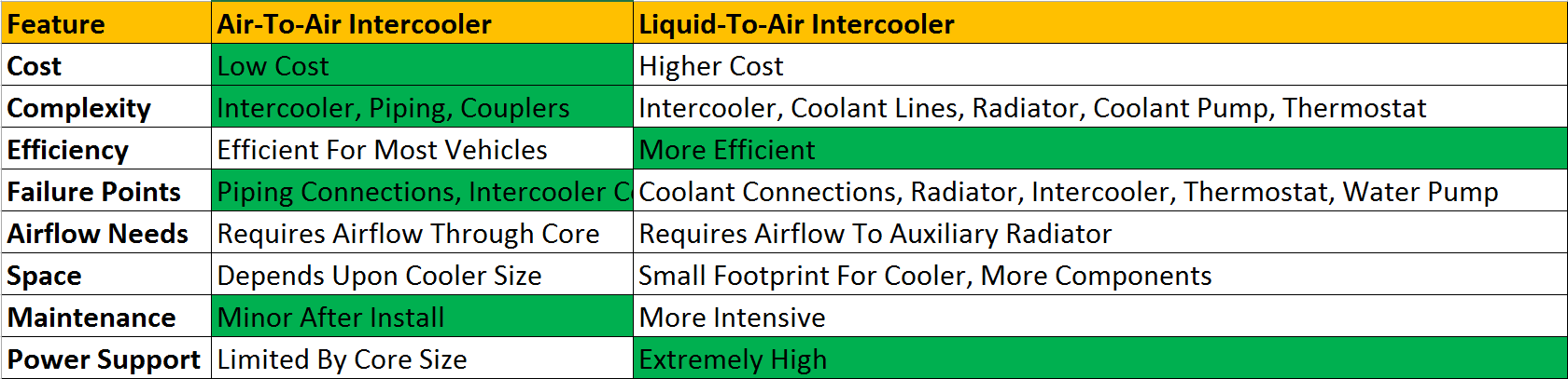
The primary drawback from purchasing a liquid setup is cost, which can be as much as two to three times the cost of an air-to-air setup, depending on the components used. As noted above, most users will be able to extract the needed cooling performance from an air-to-air setup.
3. Where's The Cooler?
Several acronyms used in intercooler discussions might confuse those not acquainted with automotive jargon. They reference the location of the intercooler and are explained below.
A. Top-Mount (TMIC)
The top-mount intercooler (TMIC) is fairly commonly used for stock heat exchangers. Two of the more popular vehicles equipped with such a system are the Subaru WRX and STI.
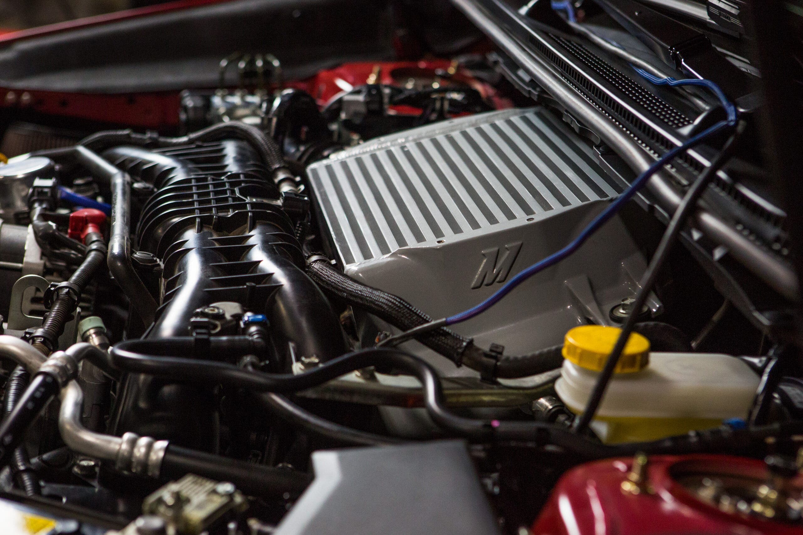
The name indicates the location of the cooler, which is on top of the engine. This type of cooler is supplied airflow via a hood scoop or some form of ducting from the front grille.

Placing the cooler in the engine bay has a few key benefits. First, this cooler is in a safe location to avoid any road debris from damaging it. Imagine you are slinging your turbocharged behemoth down a rally stage, and an errant rock decides to lodge itself in your bumper-mounted cooler. Not good. An additional benefit would be in terms of boost lag. Because the intercooler is so close to both the turbocharger and intake systems, piping will be extremely short, which allows for a shorter airflow route and less boost lag.
As with any setup, there are certainly a few downsides to a TMIC system. Heat-soak is going to be the primary problem. Since the intercooler is located within the engine bay, it will certainly be susceptible to the heat generated by your engine and exhaust system. Intake temperatures tend to rise with a TMIC at idle, which can negatively affect power output if the cooler gets too hot. Upgrading from the factory cooler to a larger bar-and-plate unit will certainly help reduce the risk of heat-soak, but the only way to eliminate it would be to select a different location for the cooler.
B. Side-Mount (SMIC)
A side-mount intercooler (SMIC) is fairly uncommon these days, but at one point it was factory equipped on a few vehicles, including the 90s DSMs, the Nissan Silvia, and a variety of VAG vehicles. This cooler could be considered a bit of a compromise between the other two choices and is typically only a factory-equipped setup. In this system, the cooler is placed toward the front of the vehicle on one of the side inlets of the bumper. Instead of blocking airflow through the center portion of the bumper, the SMIC pulls air from the side of the bumper.
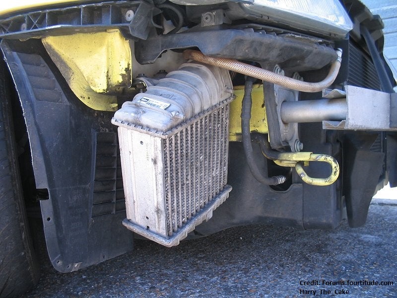
Due to space constraints, the size of this cooler is normally pretty limited, which would influence power support. Also, piping needs to be longer to route air outside the engine bay and back in. For mild builds, an upgraded SMIC will work. For anything pushing decent power, most people will prefer a more beneficial FMIC upgrade.
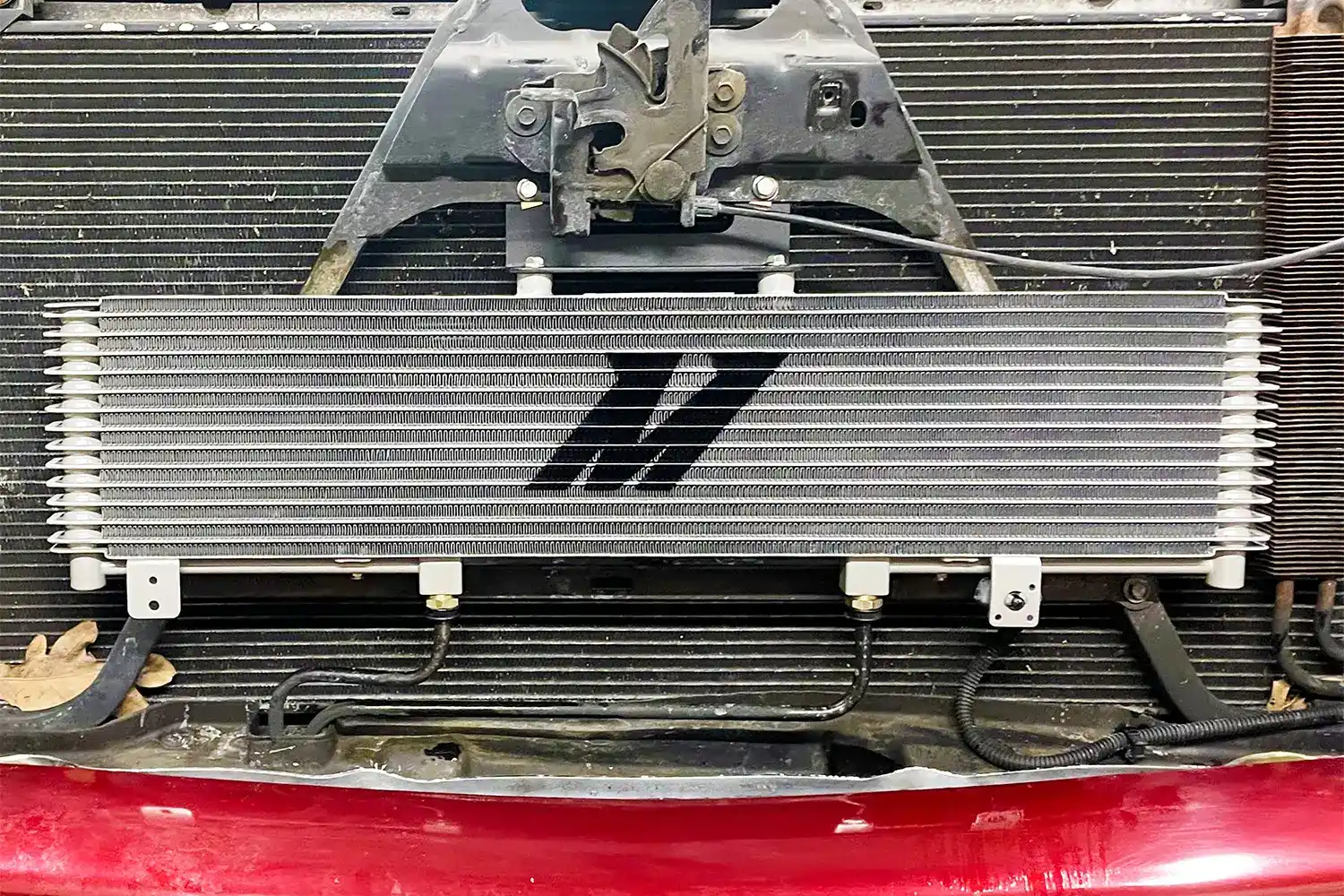
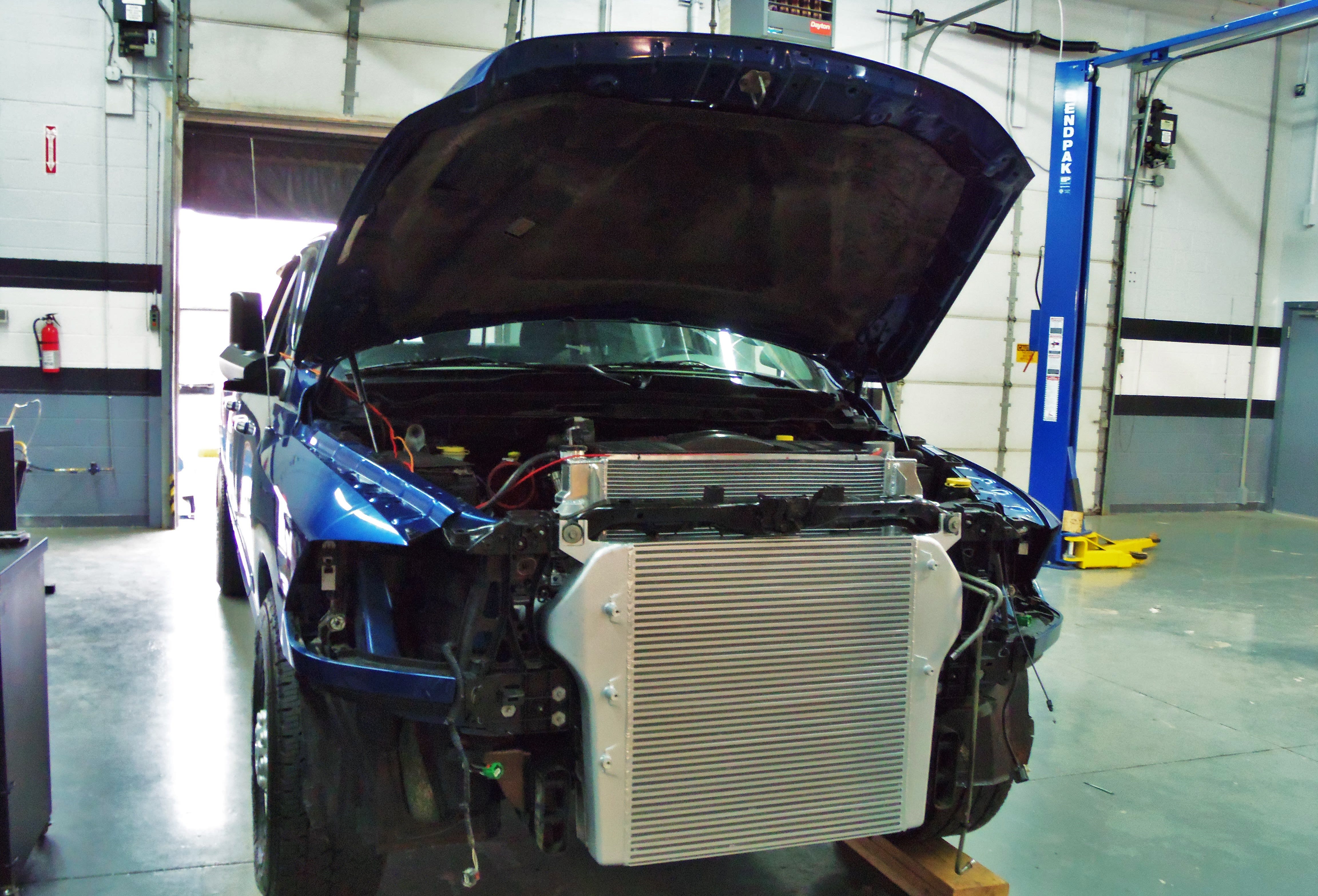
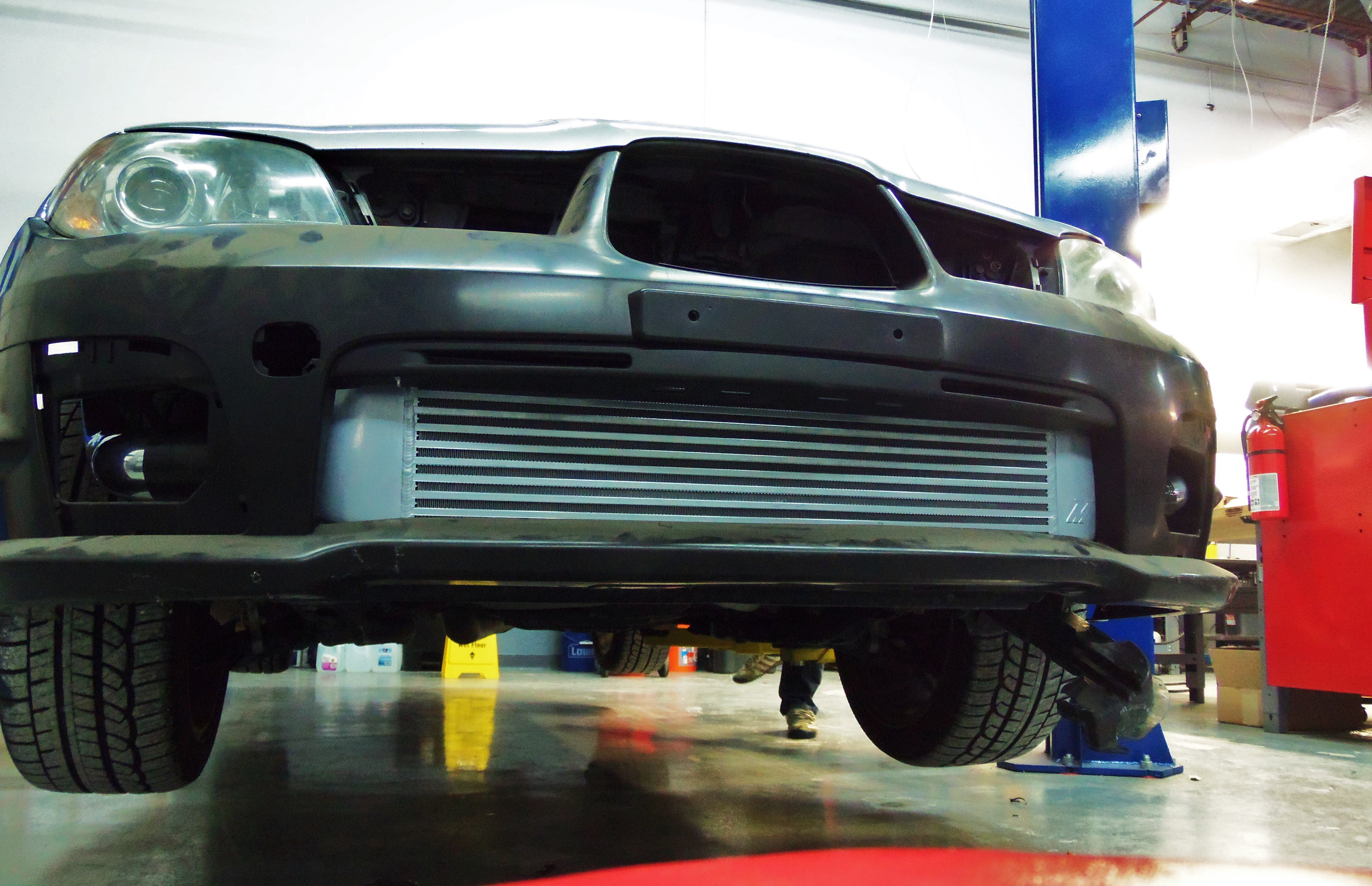
C. Front-Mount (FMIC)
A front-mount intercooler (FMIC) is not only a modification for lower intake temperatures, but it also provides some aesthetic presence. A large, bumper-mounted intercooler is an easy way to identify a fellow car guy. There are several debates regarding the use of an FMIC vs. a TMIC in terms of boost lag and actual power benefits. While a front-mount system will typically produce the lowest intake temperatures of all options, it will also incur the most boost lag. This shortcoming needs to be considered, depending on your vehicle’s power as well as your intended driving plans, but for optimal heat transfer, this is the system you want.
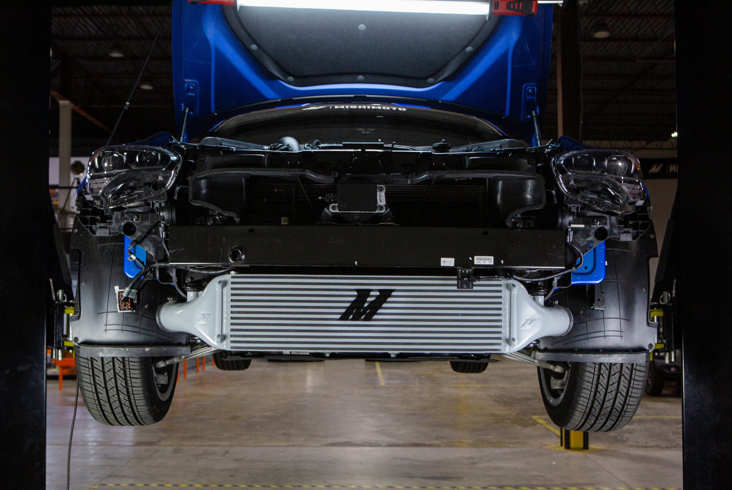
The intercooler in this system sits in the front bumper opening where it can achieve optimal airflow through the core. This cooler will impede airflow to the radiator behind it, which then causes a restriction in airflow through that heat exchanger. This setup could adversely affect coolant temperatures. It is not usually a big issue but is certainly something to keep in mind.
To summarize, your choice of intercooler setup will be dictated by your vehicle and goals. For optimal heat transfer, an FMIC is the way to go. For reduced boost lag and increased power support for mild modifications, a TMIC may be best for you.
For assistance in selecting an appropriate intercooler type for your vehicle, the best bet is to hit some enthusiasts’ forums and see what the collective groups recommend. Of course, we’re always here to help.
4. Let's Talk End Tanks
Although end tanks may seem a bit insignificant compared to the core of your intercooler, you would be surprised at the number of failures caused by poor end-tank design. Selecting the right type of end tank can help shape the long-term reliability of your heat exchanger and can also play a big role in actual airflow through the core. If your tank design is not efficient at moving the airflow your vehicle generates, you will not be able to take full advantage of that awesome core you selected!
A. Plastic
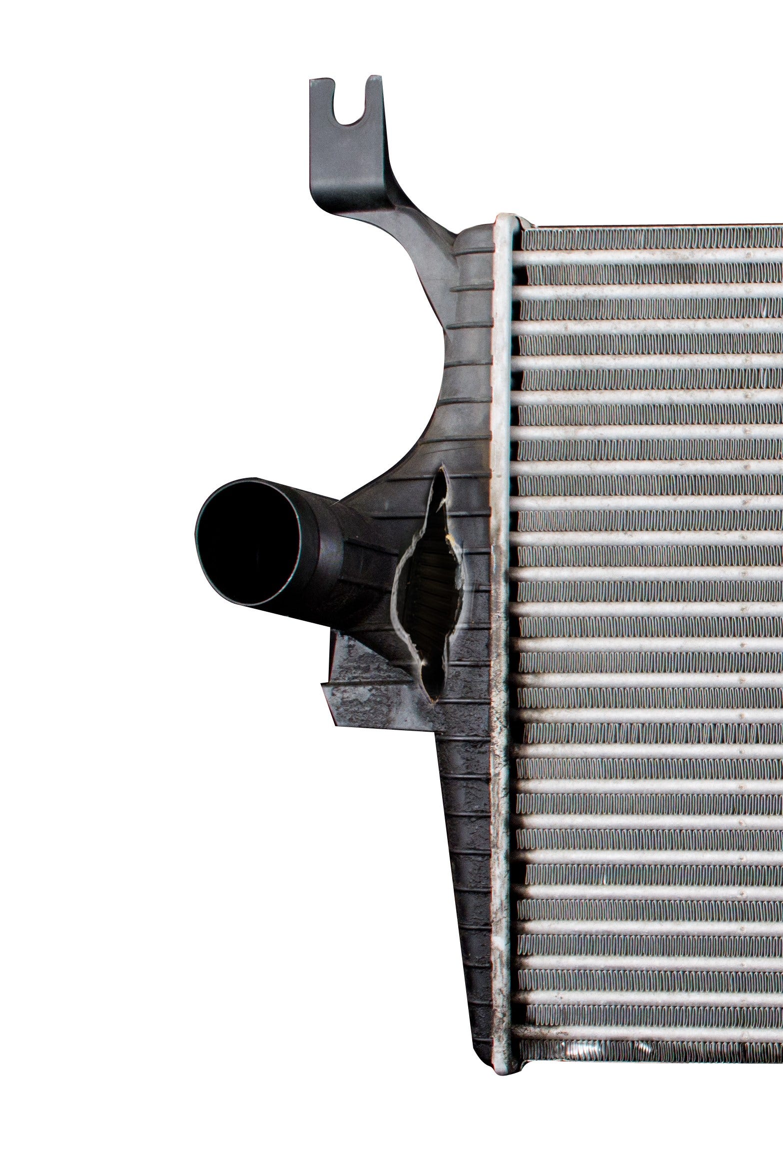
To be blunt, plastic is not what you want on a performance intercooler. Plastic end tanks are great for stock vehicles, as failures are pretty minimal … until the vehicle is modified and/or boost levels are increased. These failures are quite common with diesel trucks. A plastic end tank at a mass-produced level is far cheaper and lighter than aluminum options. Automotive manufacturers are seeking both low cost and reduced weight for just about all components on their vehicles; this likely explains why nearly all modern stock and factory vehicles are equipped with plastic tanks.
As you can imagine, plastic will begin to weaken over time as the constant variations of temperature and pressure affect its integrity and lead to eventual failure. This normally occurs in the form of a cracked or shattered end tank during a high-boost pull. When we tested this theory to check the actual pressure capacity of a plastic end-tank equipped intercooler, the result was a nice explosion. Check it out!
Along with complete failure, crimp connections can also spread with constant high boost, and will eventually cause a leak within your system. Within the crimp connection is a rubber gasket, which provides a seal between the aluminum core and the end tank. The crimps fold over on the tank to hold the two components firmly together.
Leaking connections, if small, can go undetected and result in additional wear on your turbocharger and engine. If you have an intercooler with plastic tanks, it may be wise to examine it the next time you perform vehicle maintenance. Leaking areas can usually be identified by oil seepage.
Another benefit of using plastic as a material for end-tank construction is that it is easily shaped and can be designed to provide really efficient flow. Aside from this, stick with an aluminum end tank for a performance-oriented build.
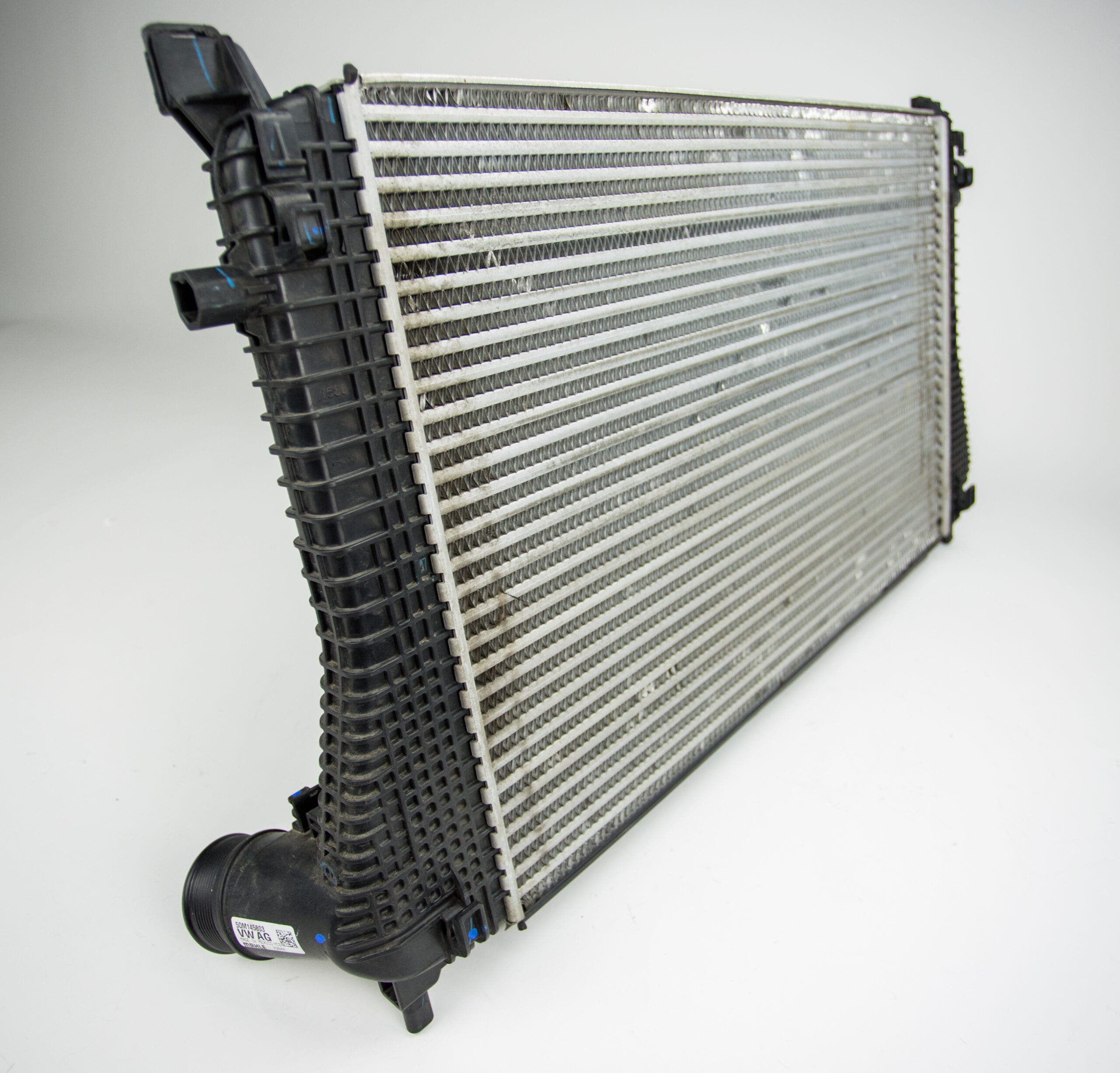
B. Stamped
Stamped aluminum end tanks are a bit of a hybrid and incorporate a lower cost (for large manufacturing runs) with the added durability of a one-piece design. These tanks can be found on older turbocharged vehicles, such as the second-generation Cummins and Mitsubishi Evolution, and are typically welded to the actual core.
Intercoolers with stamped end tanks can easily handle high boost pressures; however they are normally paired to a standard tube-and-fin core. Stamped tanks are durable and flow reasonably well, and they are far stronger than their plastic counterparts that eventually replaced them. However, they are not a typical choice (over plastic) for OEM components.
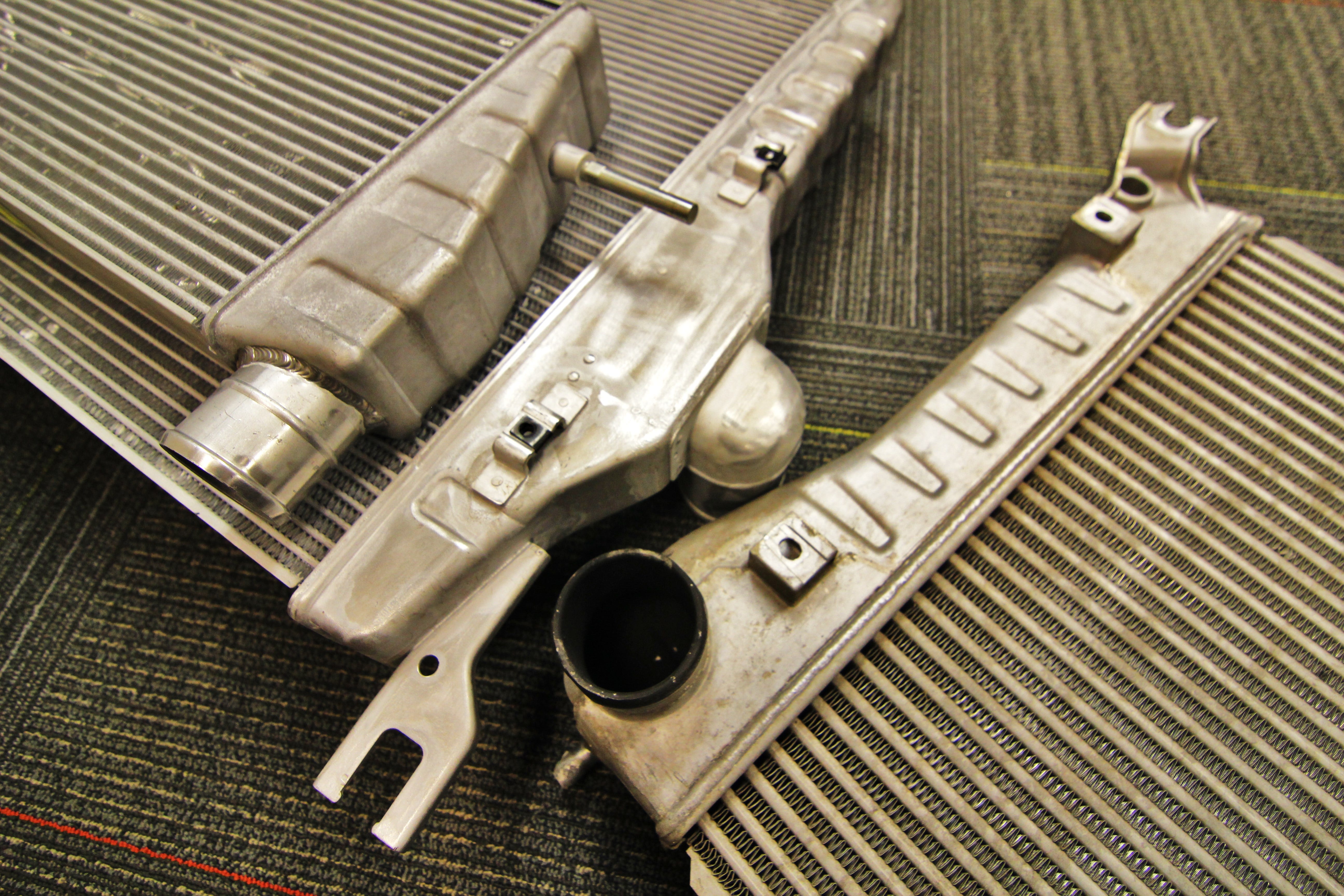
C. Cut-and-Weld Aluminum
To our eyes, a cut-and-weld intercooler tank is shadowed only by a cast-aluminum tank. You could consider the cut-and-weld as a second-best option for your vehicle. By using aluminum and welding this to the core, you eliminate the failure points associated with plastic end tanks. That said, these tanks are typically made from numerous pieces of aluminum, which allows for several potential failure points. Precision welding, proper testing, and efficient quality control processes are necessary to avoid defects with such a design. Typically, a well manufactured piece will provide fantastic durability and should withstand just about any level of boost you throw at it.
As always, there is a downside to this particular style. Being that this tank is constructed from numerous pieces of flat aluminum, it does not allow for much in terms of designing the internal surface. This means that smoothing the airflow is either quite a challenge, or not possible at all.
For most builds, a cut-and-weld tank will certainly do. But why settle for second best?
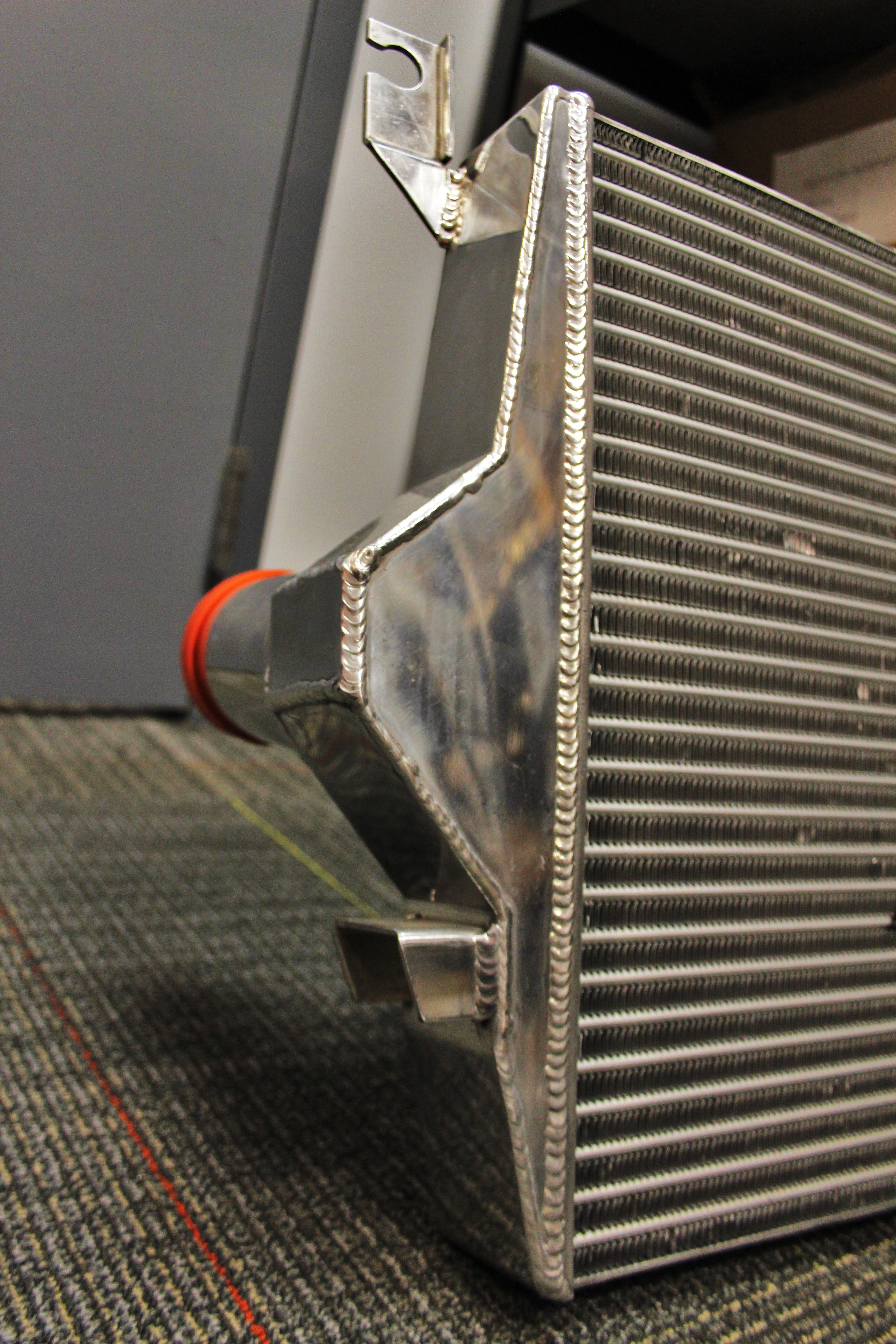
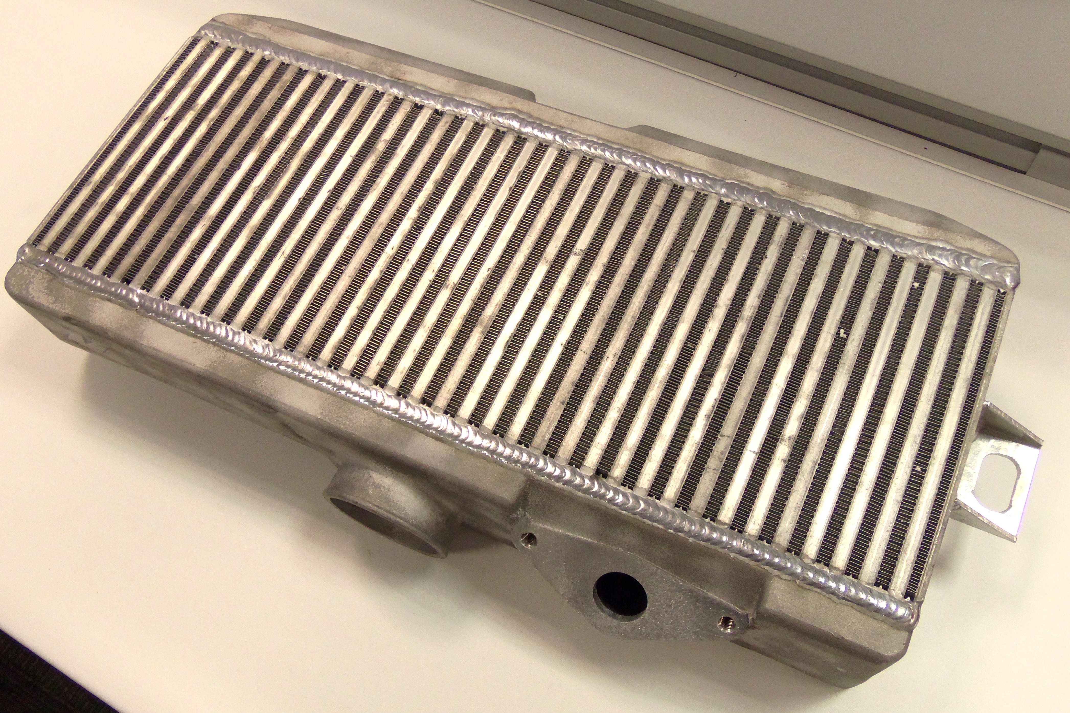
D. Cast-Aluminum
I certainly don’t want to push you into making a decision, but this is the end tank you want for a build requiring nothing but the best. Combining the best points in reliability and flow, a cast-aluminum end tank is at the top of our list. It has a one-piece aluminum design that is TIG welded to the core of the cooler. Check out a few castings from our 2008–2014 STI intercooler.
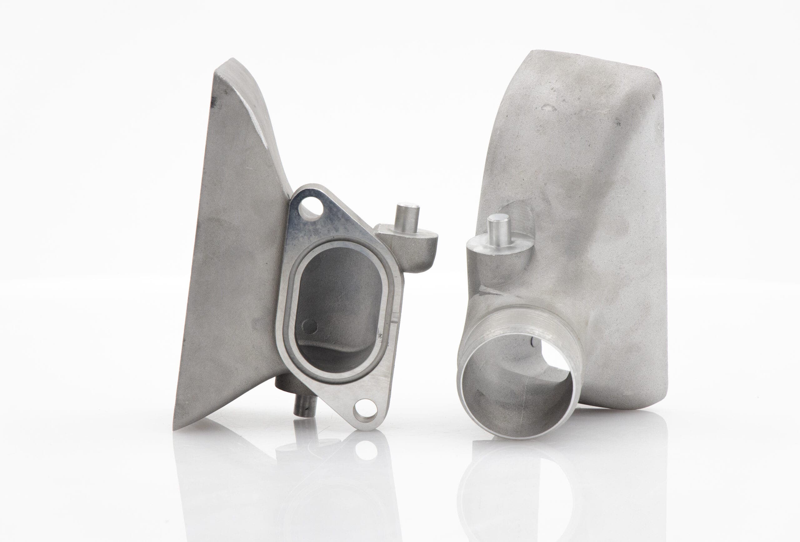
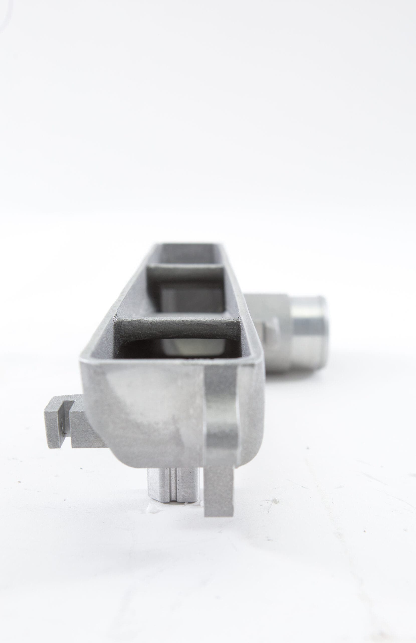
This design eliminates failure points from crimp connections, poor welds on a cut-and-weld unit, or blown-out plastic tanks. Thickness of an end tank can vary depending on the pressure requirements; we typically design our tanks with a 4mm wall thickness. This means that you can run any automotive/diesel boost pressure without concern of destroying the tank. If you can manage to do so, however, please send us pictures!
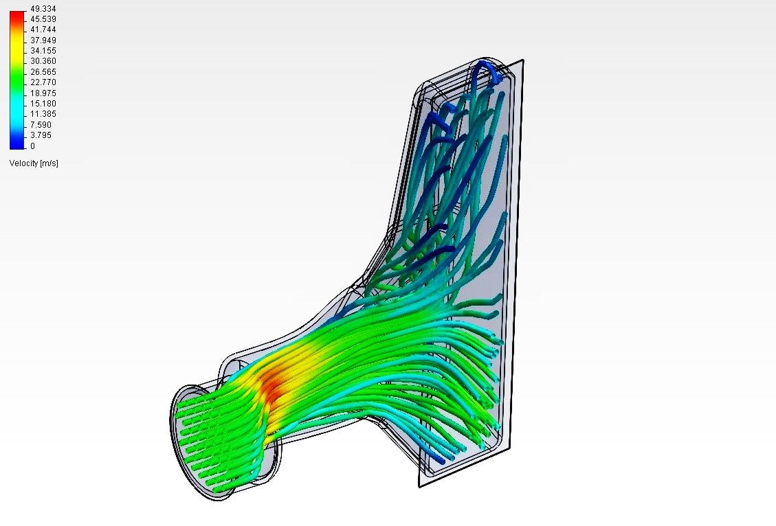
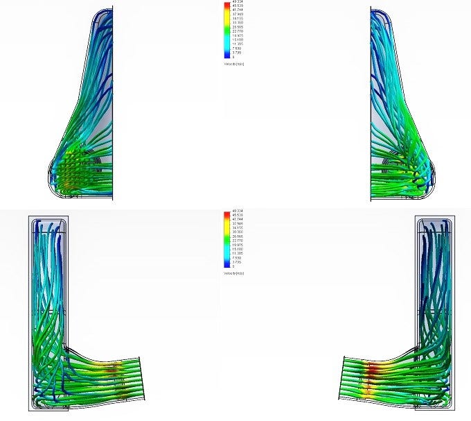
Along with a more robust construction, this tank design allows product engineers to optimize flow. For instance, Mishimoto engineers use CFD software to ensure the tank provides flow to the entire length of the core, dispersing the air to utilize the entire core. This is especially important for intercoolers that are very tall. On top of this, we can even cast air diverters into the internal portion of the tank to push airflow to portions of the core where it would not otherwise reach.
All this innovation results in greater heat transfer. Even if the impact is only the drop of a few degrees in intake temperatures, we find value in spending the time to create a cooler that we know is our best work.
In-short, a cast aluminum end tank is going to be the ideal choice from both an engineering standpoint as well as from a consumer decision-making point.
5. Core Construction (Or, the Value of a Good Core)
Selecting a solid, efficient core is the primary concern when choosing an intercooler for your vehicle. One cooler is not the absolute best for every vehicle. Airflow, boost pressure, and engine displacement will all play a role in how an intercooler has an impact on the performance of your vehicle.
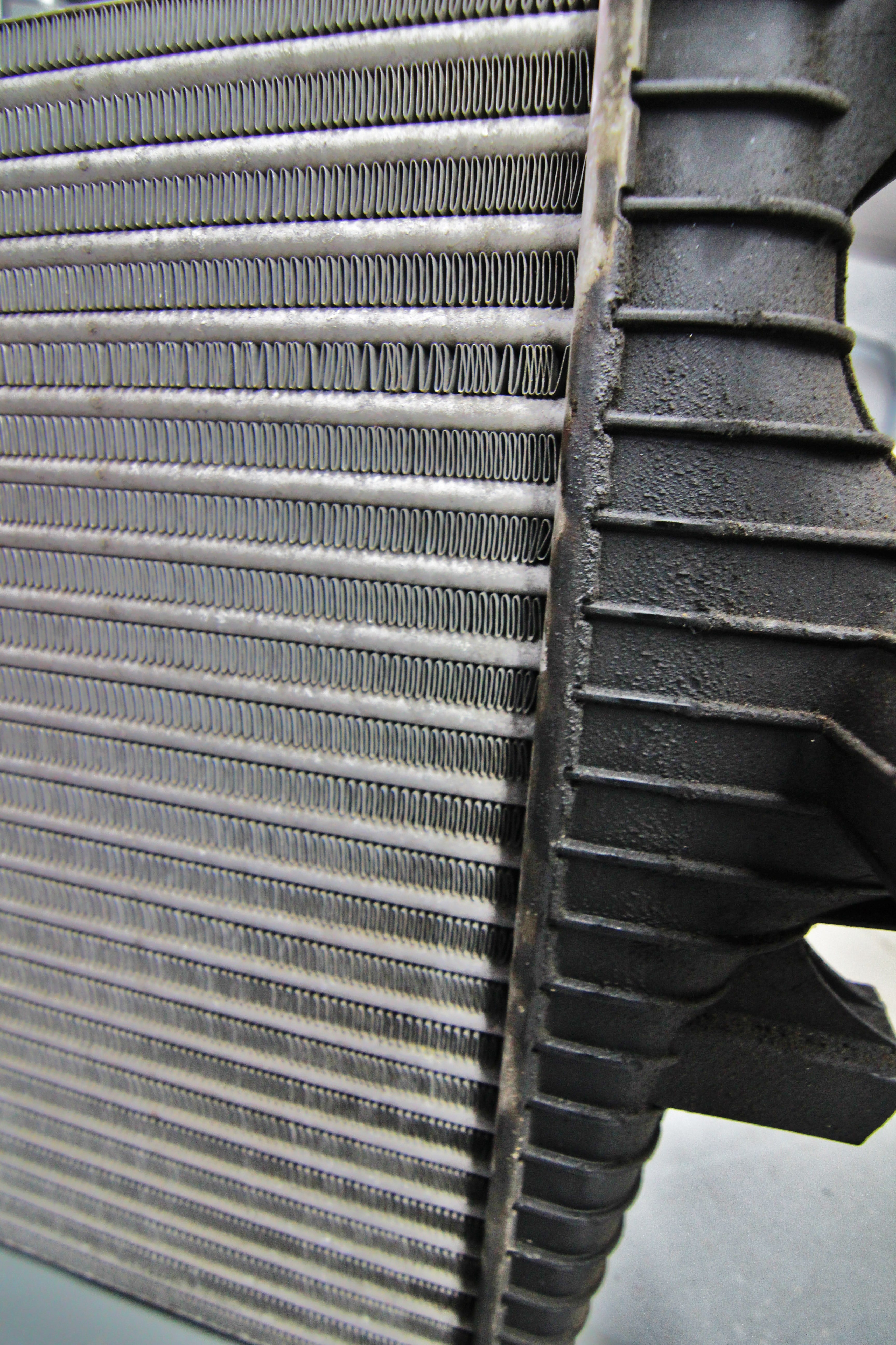
A. Tube-and-Fin vs. Bar-and-Plate
One of the big online discussions regarding intercooler cores is the tube-and-fin vs. bar-and-plate debate. Which do you want? Why is one better than the other? All valid questions here.
Tube-and-fin cores are used on stock intercoolers and are not commonly used for aftermarket units. These coolers are far lighter than the alternative, and are also less expensive to manufacture. (We keep touching on this because it is important to keep in mind when considering why certain components are used by OE manufacturers). The number one reason why tube-and-fin cores are ditched on aftermarket coolers is heat dissipation. Ever heard of heat-soak?
Heat-soak can occur when an intercooler experiences either very warm ambient temperatures, such as a hot engine bay, or repeated pulls that cause the cooler to become overheated. This can then result in power output losses as the ECU adjusts (pulls timing) for the high intake temperatures. Heat-soak is certainly a bad thing. A bar-and-plate intercooler can typically tolerate far more abuse with repeated heating without becoming inefficient. This is especially helpful for vehicles seeing track duty that will be in boost for the better part of longer-duration track lapping. I am talking to you road course guys.
On top of this, a bar-and-plate core is more efficient in transferring heat in general. The design of the bar-and-plate allows for a significantly thinner material containing the airflow, which aids in producing greater heat transfer.
If you are performance driven and not too concerned about adding a few pounds to your vehicle, this is the core style for you. Check out the basic comparison chart below.
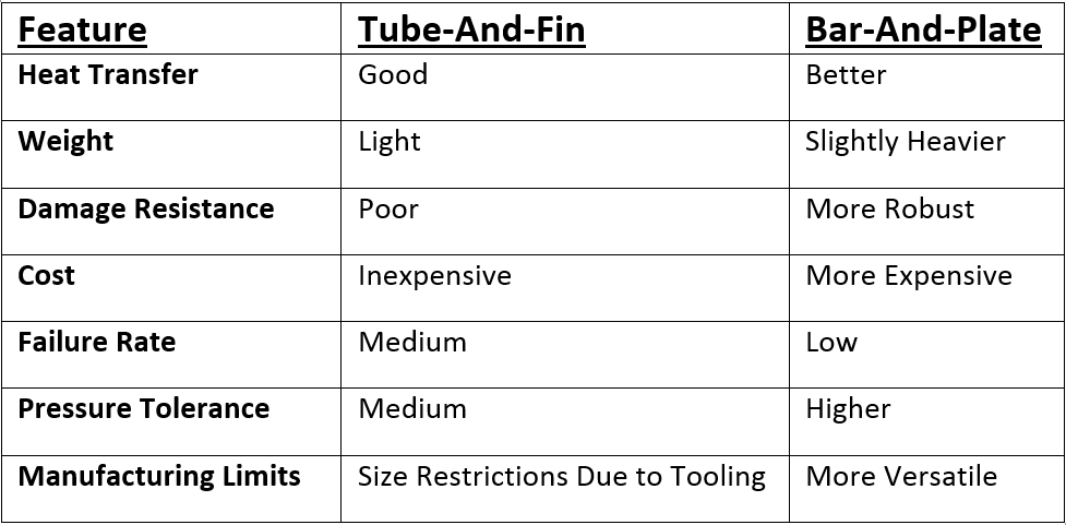
For a high percentage of folks paying close attention to intercooler choice, a bar-and-plate design is the go-to and will provide far superior performance in nearly all applications.
B. Fin Styles
Why are these things so complex? I just want an intercooler. Yes, we are getting quite in-depth here, but keep in mind that every single feature of your intercooler is important. We wouldn’t make these recommendations if they weren’t valid. Fins, both internal and external, are available in a few different styles depending on the goals of the cooler itself. For automotive intercoolers, you will typically see either a plain straight fin or an offset-style fin. These are best explained by images.
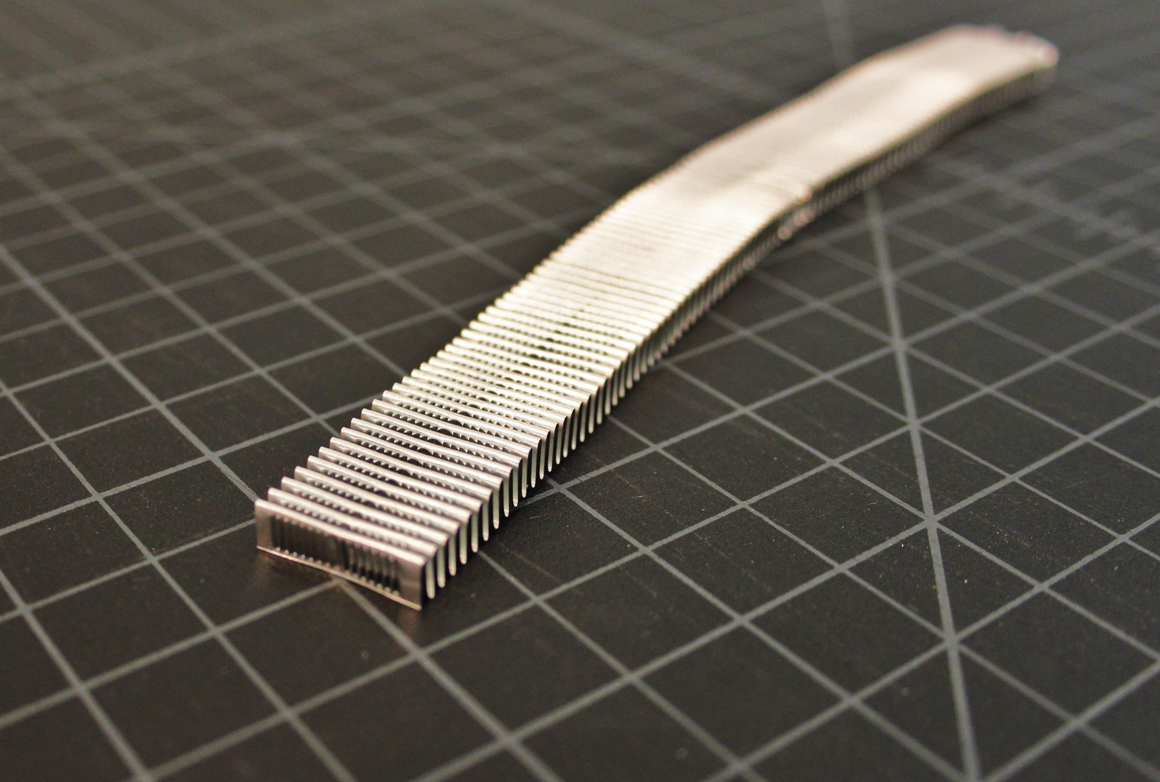
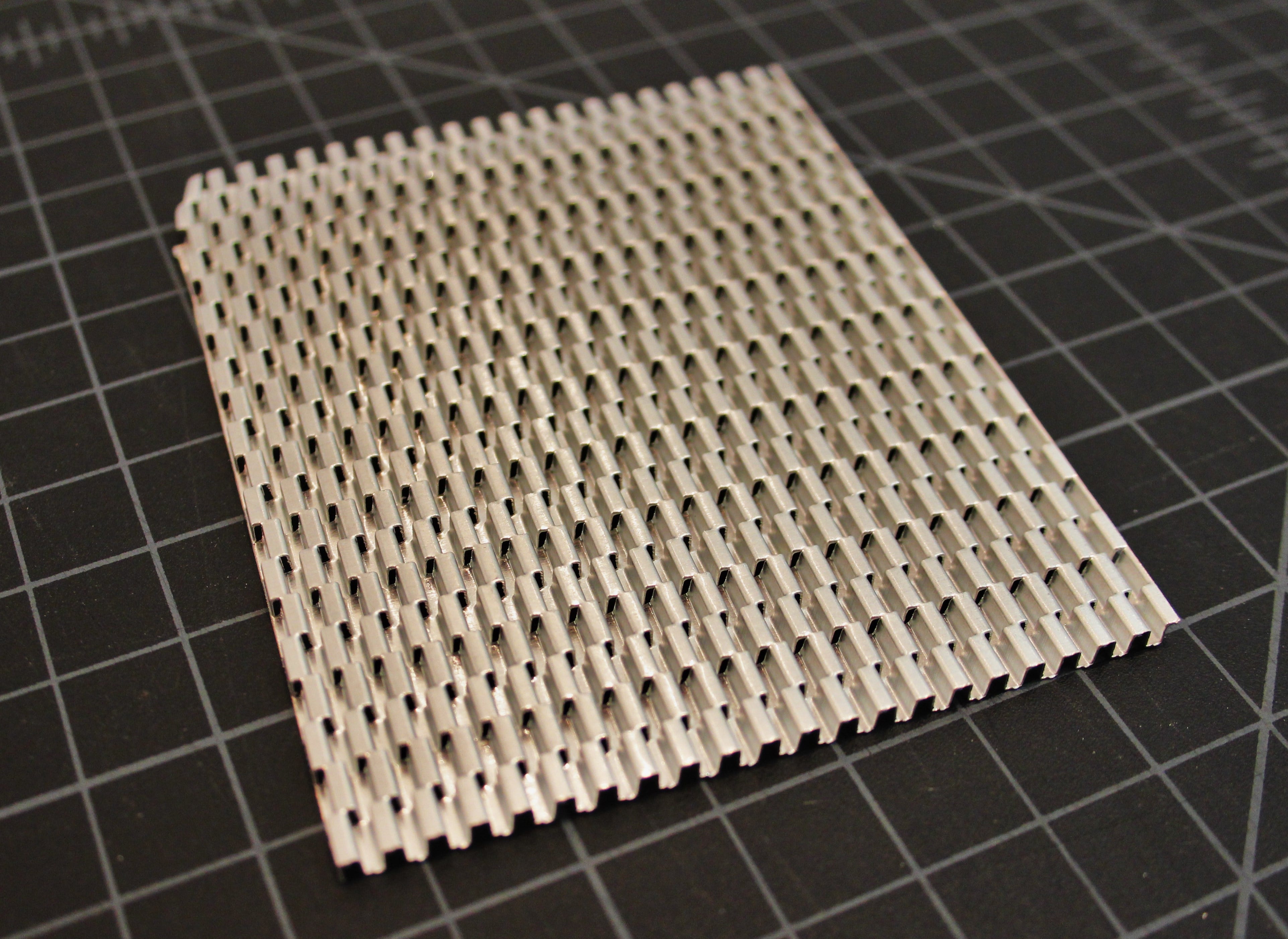
As you can see, the offset style fin appears to provide far more surface area for air contact. This arrangement will force air to split numerous times on its path through the core, which amplifies the amount of heat exchange that can occur. Along with improving heat transfer, this will also result in greater pressure loss, which is something that you will need to consider. In general, Mishimoto intercoolers utilize an offset fin to enhance the exchange of heat as much as possible.
C. Fin Density
When it comes to intercooler design, fins are a make-or-break component that can make the difference between an efficient cooler and one that belongs in the garbage. As we’ve noted numerous times, more fins equals greater heat exchange; however, this is at the expense of airflow and restriction. Weighing these can be a challenge, but that’s why we have testing and an engineering team.
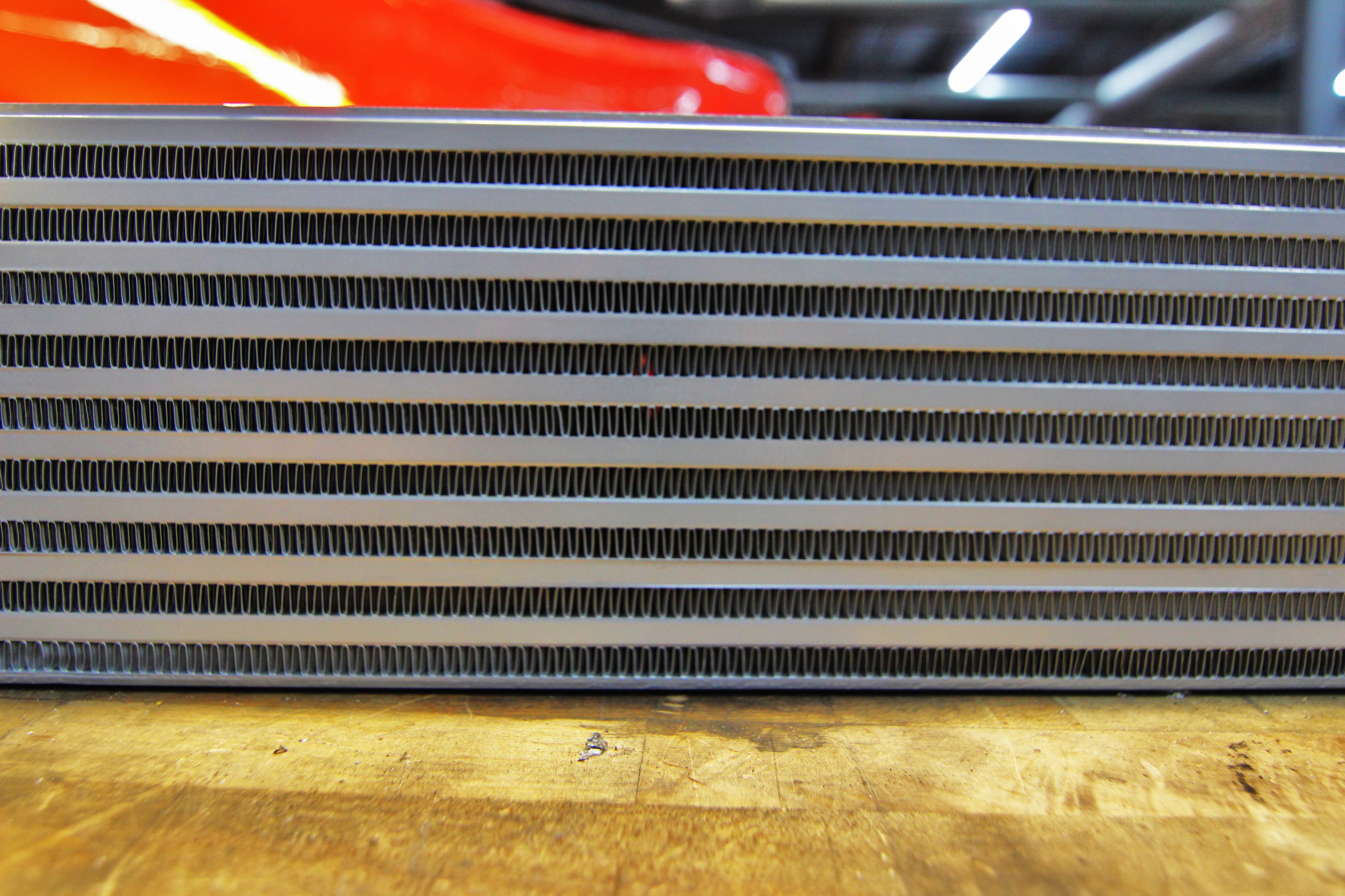
In general, identifying a dense core is rather simple.
To improve density we can modify both the height and pitch of the fins to create differences in overall fin surface area. We normally create a few prototypes with different variations to put our theories to the test on actual dyno runs.
Fins per inch (FPI) can vary significantly both internally and externally. Both need to be evaluated based on airflow hitting the external surface of the core, as well as airflow moving through the cooler from the turbocharger. Our engineering team uses a variety of equations to come to determine which prototypes will be used for testing. We can then use our data to improve our process for future product development, allowing us to achieve the most accurate results possible.
In general, Mishimoto intercoolers utilize an offset-style internal fin and a louvered straight fin for the external airflow. This configuration provides turbulence within the cooler for improved heat transfer, and allows for ambient airflow to pass easily through the external fins of the core. Fin pitch and height are typically similar for internal and external fins; the primary difference is the style of fin.
D. Optimal Airflow (Core Placement)
This should go without saying, but one important factor for cooler performance is airflow (air-to-air, specifically). If you hide your intercooler behind a bumper or another heat exchanger, do keep in mind that this will impede flow and have an impact on cooling efficiency. If you place the cooler in a location receiving direct airflow, it will allow you to take full advantage of that awesome cooler you picked out for your build! Just another thing to keep in mind when sizing your core.
6. Let It Breathe! Inlet and Outlet Sizing!
Intercooler inlet and outlet sizing may not seem extremely important; but it is certainly something to consider when planning your system. For one, you will want to match your piping to these inlet and outlet sizes to ensure smooth airflow. Otherwise, you will require transition couplers, which is not the end of the world but should be avoided if possible. Airflow volume and horsepower output are two key specs that you can use to determine the size of your cooler inlet and outlet. Piping too large will require greater flow to produce boost, causing lag. Piping too small will restrict flow and limit power output. Typically you would want to run the smallest piping possible without causing restrictions. The chart below shows maximum horsepower and CFM for each particular piping size.
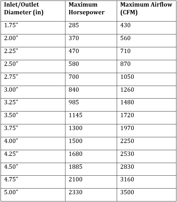
As you can see, smaller piping is actually quite capable of supporting reasonable power numbers. 3.0” piping will provide the necessary flow for up to 840 hp, which is going to handle a majority of vehicle setups. If you are running piping larger than this, it might be a good idea to take a look at the chart above to consider redesigning your system for greater efficiency and reduced lag.
A. Staggered Inlet and Outlet Sizing
Some folks decide to run larger piping and/or connection points on the cold-side of the system. This increase in size helps the system maintain flow after the pressure loss created by the intercooler core. The impact of this will depend on the amount of power and flow your engine is producing, but it does indeed produce positive results. We use a similar piping diameter setup on our 2001–2014 Subaru front-mount intercooler kits, which features 2.25” hot-side piping and 2.75” cold-side piping.
For a budget build or a low-boost setup where pressure drop is not a concern, I would not worry about staggering the tubing size. However, if you want the most efficient system for your vehicle and expect a decent amount of pressure drop from a large cooler, then incorporating larger cold-side piping is a wise move.
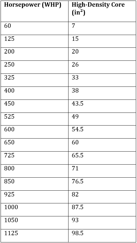
7. Bigger is Not Always Better (When Lag Strikes Back)
Another important size-related component to consider is the core surface area of the intercooler you have selected. Similar to the issue of inlet size, you want an intercooler properly sized to provide efficient cooling without having an impact on boost lag. The larger the core volume, the more air is required to fill the cooler. As with the piping size, we can equate this to a chart that can help you choose the correct size intercooler for your project.
8. Surface Finish
Surface finish is a bit debatable within the realm of heat exchangers. While some folks may prefer a raw aluminum finish, most will appreciate a paint or coating that protects the surface and provides a more aesthetically pleasing appearance.
So, two questions immediately come to mind. What finish will be the most durable? What finish will provide the best performance in terms of heat transfer?
For aluminum coolers, there are three common coatings.
- Painted
- Powder-Coated
- Anodized
We will discuss these coatings individually below.
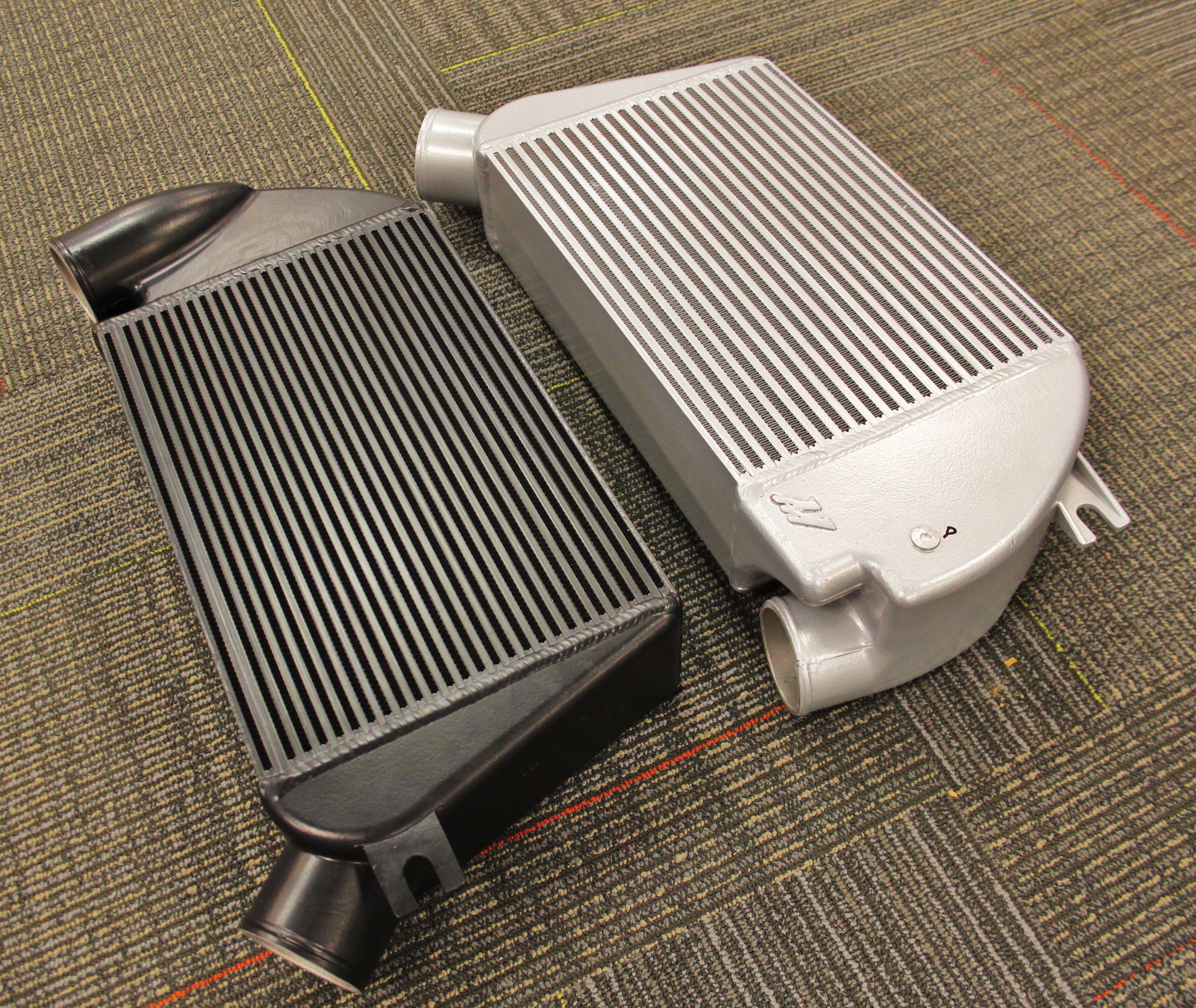
A. Powder-Coated
Powder coating is our typical go-to finish for all the intercoolers we currently offer. Not only does it look great, but it also provides a very durable finish that is resistant to damage from road debris (which can be quite common on vehicles with an FMIC). Powder coating uses an electric charge, sprayable paint in the form of a dry material, and an oven to bake the paint into the surface. As with any form of painting, surface preparation is key to a smooth, even, and strong coat. Once prepared, the paint is electrostatically charged and is applied to the cooler.
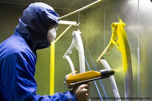
Following the coating, the paint is baked in an oven so that the particles melt and coalesce to attach to the surface. This finish seems to be pretty popular for nearly all automotive components including chassis parts, external engine components, and suspension bits. We have had great success in powder coating our intercoolers, and we find it to be a great process that provides fantastic durability and a great looking finish.
B. Painted
Wet painting an intercooler is also another option for a reasonably durable finish. Although it will not provide the resilience of the other finish types, painting will do the job (if correctly applied) and is rather inexpensive.
It is also a less intensive process and does not require an electrical charge or a high-temperature oven for curing. Painting the cooler requires light coats to ensure that the external fins do not become clogged. This would have an impact on airflow through the core and could reduce heat transfer. As with powder coating, surface preparation and cleanliness are key in creating a nicely painted, finished product.
C. Anodized
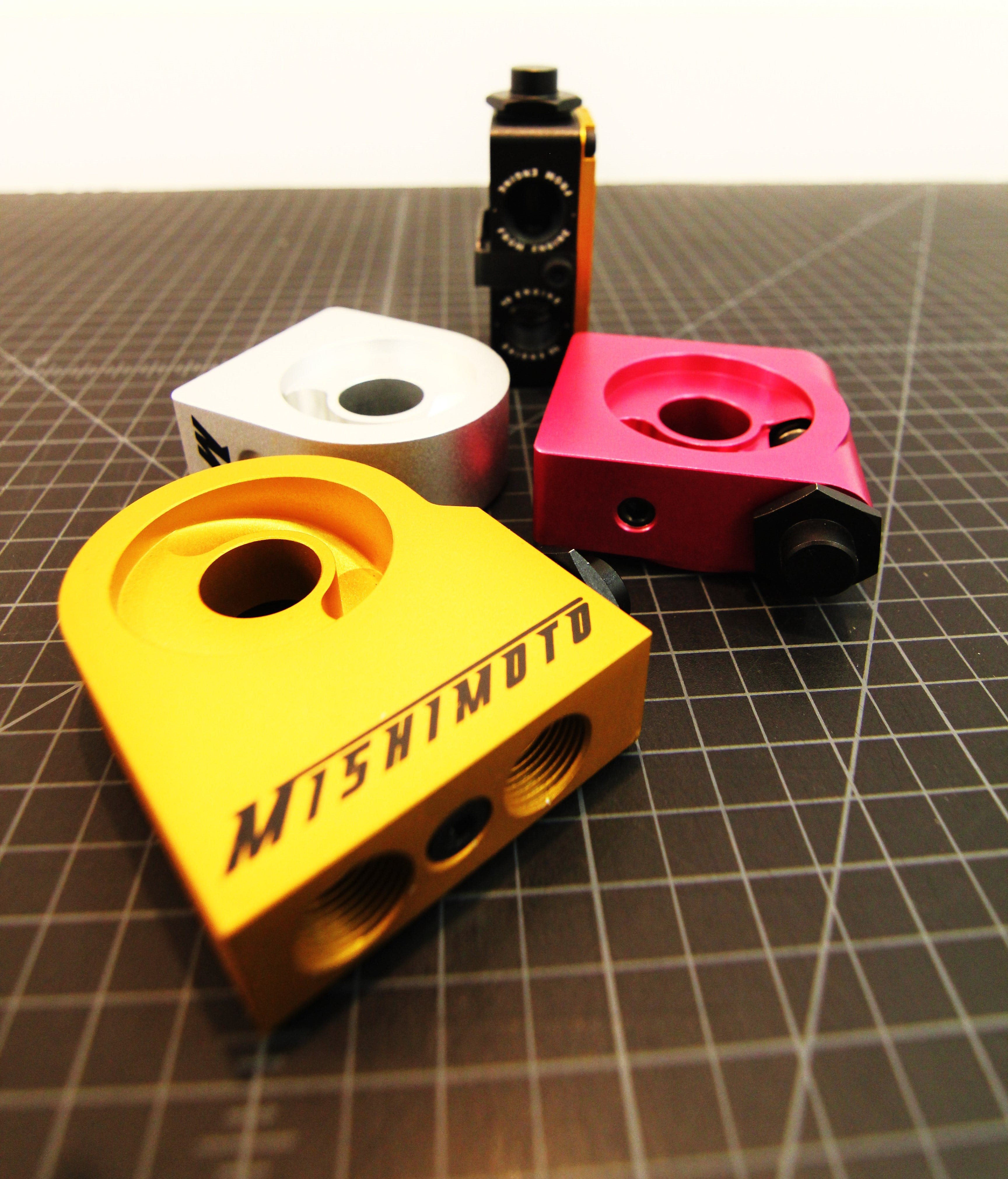
Anodizing is a pretty slick process that is typically reserved for nonferrous metals such as aluminum and titanium. Although there are a few different processes for anodizing, the general routine includes pretreatment and cleaning in an alkaline detergent, an acid bath to remove alloys on the surface, the electrical anodizing process, a coloring process, and then a sealing process within a chemical bath to seal the pore openings within the coating. This is the most involved process and is typically more expensive, especially for small batches of components. For a heat exchanger such as an intercooler, great attention must be given to the acidic process to ensure that the thin fins within the core are not damaged or eroded. An example would be our anodized oil sandwich plates and in-line thermostat, which are both utilized in our direct-fit oil cooler solutions.
One of the downsides of anodization would be the properties related to color fading. Anodized surfaces can fade and oxidize from exposure to UV rays. Depending on the quality of the sealer, this can occur from one to five years of UV exposure.
D. Durability
The primary reason for coating an intercooler is to provide a durable surface that will be resistant to damage. All the finishes above will provide some form of protection. A painted surface is far more likely to peel or scratch compared to the other two options. We select powder coating because it provides a thicker surface covering that is less likely to scratch. Anodized finishes will scratch, but the tint is integrated into the underlying aluminum, thus providing a very resistant finish. Picking between a powder coat and anodized finish can be a challenge. Both finishes offer great protection and should remain intact on the intercooler.
E. Heat Transfer
This is one of those arguments that has been around for quite some time. In general, any intercooler coating will have a minimal impact on actual cooling efficiency. Additionally, the color of the coating will not cause an appreciable difference in heat transfer. An intercooler cools by convection, and the insulating layer of protection will not provide a noticeable difference in performance. We actually conducted a test on both a raw and painted intercooler to evaluate any differences in temperature or power output. Our results indicated that both were essentially identical!
We opt to powder coat our intercoolers for improved aesthetics and resistance to corrosion.
Feel free to select whichever you prefer in terms of aesthetics and cost.
9. Maintenance
Intercooler maintenance should be relatively minimal in most cases, especially for an air-to-air cooler. Recommended maintenance processes are noted below.
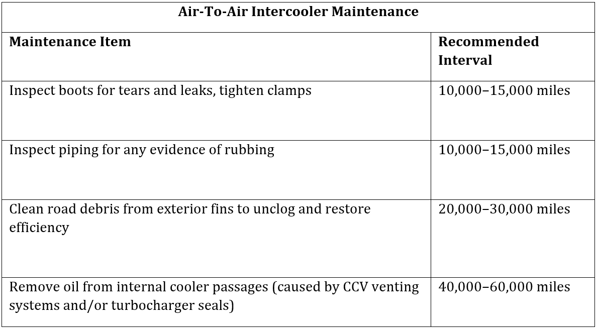
As you can see, these maintenance items are not frequent or time consuming. By following this guide you can retain the efficiency of your system and reduce the chance of vehicle downtime. Intervals are based on normal driving conditions; extreme conditions may require more frequent inspections.
We cover additional details regarding internal cleaning of the piping and charge-air cooler in our intercooler boot-oriented article linked below.
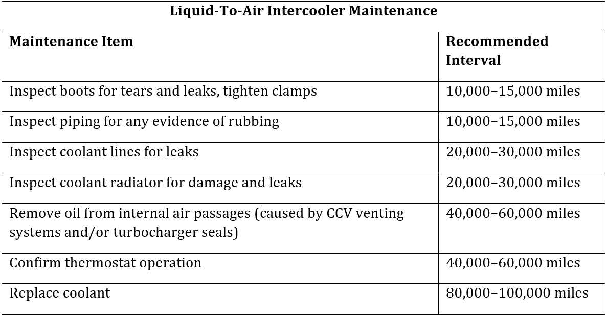
Although the maintenance for a liquid-to-air system is more intensive, do keep in mind that both systems are fairly hassle-free, implying that quality components are used and the system is properly designed and installed. In general though, a charge-air-cooler system should not require substantial maintenance or upkeep.
10. Leaks
Leaks within the CAC system are usually located within the piping or boost tubes. That said, road damage can certainly cause the core of a cooler to leak boost. Another potential leak point result from placing too much boost within a cooler not designed to do so. We discussed earlier that plastic end tanks can crack or explode when a massive amount of pressure is introduced. This type of failure is usually substantial and results in a nonrunning vehicle. Small leaks are also detrimental to your system and engine in general.
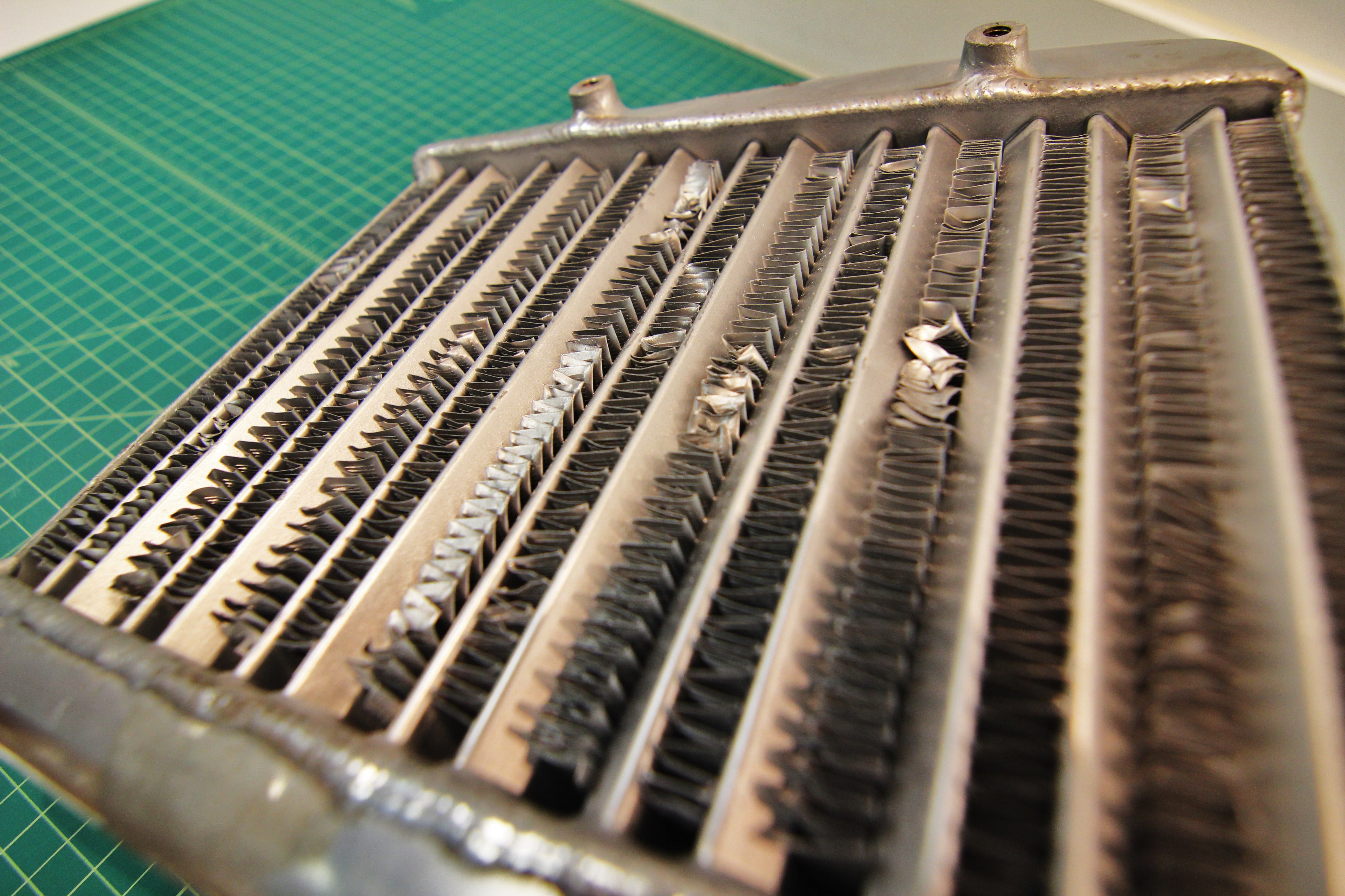
Damaged fins can cause reduced efficiency, as the bends may restrict airflow. It is possible to straighten slightly bent fins either with a tweezer, a plastic fork, or specifically designed fin straightener tools.
A small leak may go undetected, but your ECU will still demand that boost pressures meet the requested amount. To do so, your turbocharger will be working harder to account for leaking pressure. This can cause additional wear and heat, which can reduce the lifespan of your turbocharger and cause potential engine damage. If a small leak is detected, it is highly recommended that you address the issue as quickly as possible. Repairing core damage is usually not possible and requires replacement of the cooler. Do not let a leak interfere with the efficiency of your intercooler system.
11. Testing
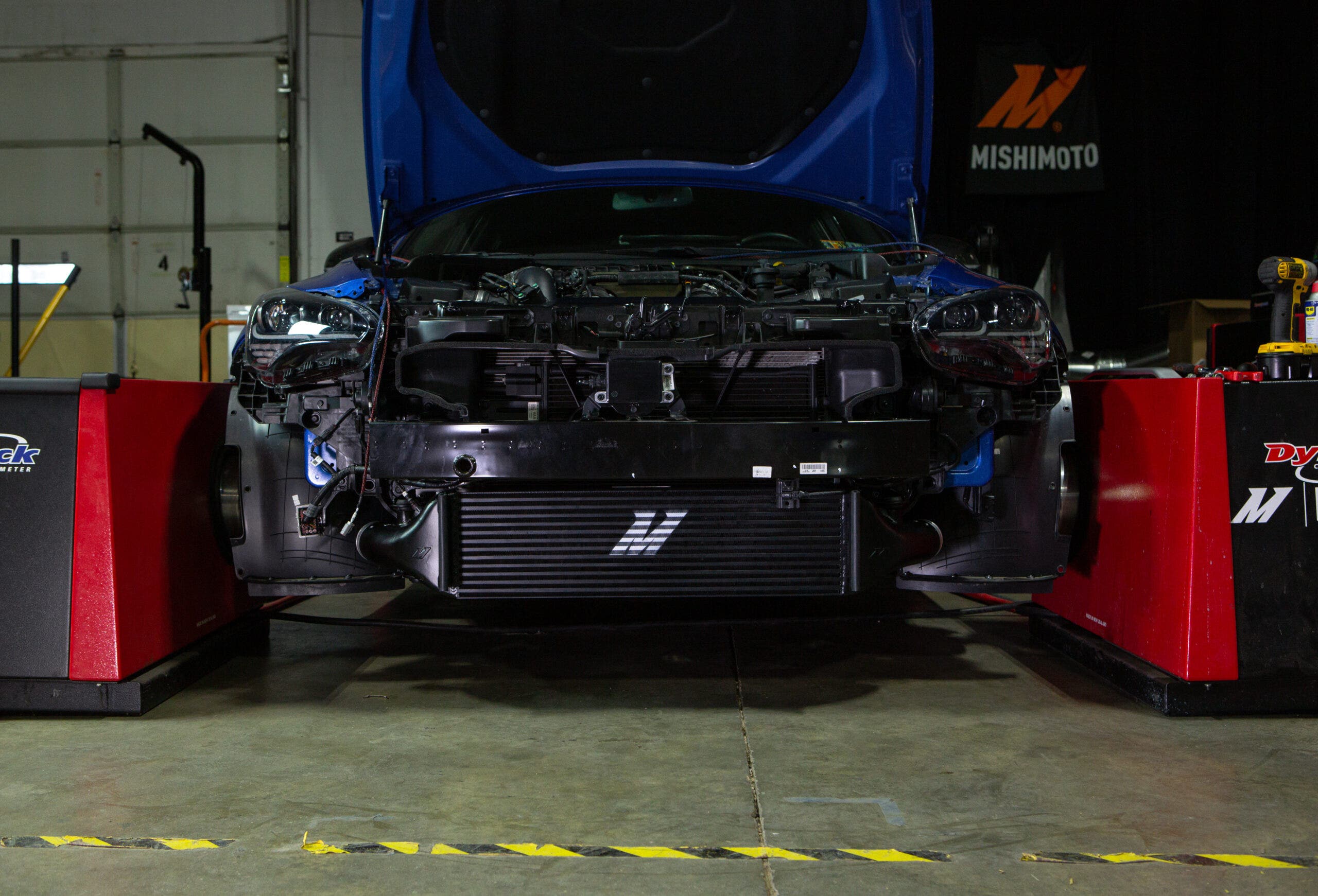
Throwing an intercooler on your vehicle is quick and typically a pretty easy upgrade. But how do you know you are getting the most from the cooler you purchased? Proper testing is key, whether it be from your personal data logs or from efficiency data from the manufacturer. Regardless of who conducts the tests, you want to ensure that the intercooler is up to the task of managing the temperatures produced by your righteous build!
Here at Mishimoto, we perform extensive testing for each new intercooler developed to ensure that we are producing appropriate intake temperatures and minimal pressure drop. On top of that, we also like to see what kind of power output increases we can manage with the cooler temperatures. Check out details on our testing processes discussed below.
A. Intake Temperatures & Efficiency
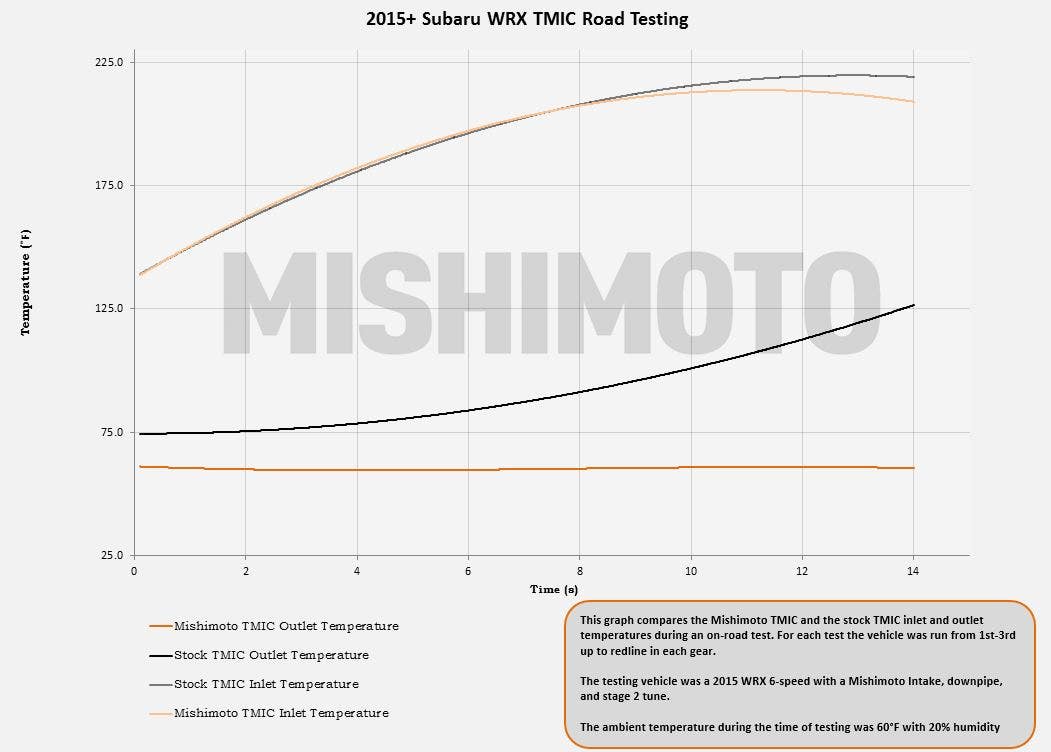
We’ve harped on it and you are sick of hearing it I’m sure, but intake temperature reduction is the primary goal for any intercooler upgrade. Evaluating this is reasonably simple for a facility equipped with the appropriate testing provisions. A temperature sensor is installed in both the hot-side and cold-side of the intercooler to evaluate the change in temperature occurring within the cooler itself.
For direct-fit intercooler upgrades, we typically perform an identical test with both the stock and prototype coolers to check for differences in outlet temperatures. On average, we are able to drop temperatures in our coolers by 10%–40% compared to stock intercoolers. The goal with this test is to reduce temperatures as close to ambient (outside temperature) as possible. Once the testing is complete, we can produce a chart depicting the difference in temperature over time or rpm. Check out the plot below from our recent testing of our 2015 WRX equipped with a TMIC.
B. Pressure Drop
Pressure drop is yet another necessary consideration during both development and testing. Similar to the temperature data collection, we install pressure sensors on the inlet and outlet of the cooler in order to gauge the loss from one side to the other. Pressure loss in some form is going to occur, but keeping it to a minimum is the goal. With a dense core packed with cooling fins, airflow will be disturbed in some manner, which results in the loss of pressure we see in our results. The goal at Mishimoto is to reduce pressure loss as much as possible compared to the stock cooler, while still producing temperature drops.
C. Power Output
Power output is a bit of a strange statistic for an intercooler upgrade. Most people would consider the intercooler component as a supporting modification to reduce temperatures created by larger turbochargers, create more boost, and allow for more aggressive tuning. Power gains can certainly occur on a stock tune due to the reduced intake temperatures and adjustment from the ECU. So, from time to time we will see power gains when bolting our cooler onto a vehicle utilizing a stock tune.
Most power gains will be achieved through a vehicle-specific tune that allows the user to take full advantage of the lower intake temperatures. Gains will vary based on many vehicle and engine factors.
12. Conclusion
We’ve provided quite a lot of information here, which may not be easy to digest in one go. Please refer to this guide as much as needed to help provide direction for your intercooler selection. Following the basic guidelines noted below and covered above should ensure that you end up with a cooler that elevates the performance of your boosted V8, inline 6, flat four, or 5 cylinder (for you wacky Germans and Swedes).
When choosing an intercooler:
- Pick the correct style cooler for your needs (liquid-to-air or air-to-air).
- Place the cooler in a location with ample airflow (air-to-air).
- Be sure that the end tanks flow properly and will handle your intended boost levels.
- Select an efficient core.
- Be sure that piping and inlet/outlet diameters will produce efficient airflow.
- Select a core of appropriate size.
- Look for product testing data provided by the manufacturer.
- Be sure the finish is properly protected.
- Stay on top of CAC system maintenance for optimal performance.
Good luck and feel free to contact our team for further advice on picking a cooler for your build. Be sure you read this first though, as there will be a quiz!
Thanks
–John