We Struck Oil - Catch Can R&D, Part 2: The Mock-Up
Are you a nerd for up-and-coming tech? I am. Technology is awesome. Let's just start there. It's wild to think that we are approaching the 10-year anniversary of the iPhone's first introduction (June 29, 2007, per the all-knowing Wikipedia). As we enter 2017, autonomous vehicles are gaining mainstream traction, rockets can (sort of) land themselves intact, human head transplants will become a thing, and we can now "like" Instagram comments. What a time to be alive! Mishimoto is fully embracing the exponential upward curve of this tech advancement.
Our direct-fit catch can kits are quickly becoming some of the best on the market, so I must say, we are getting good at this. It's all due to our incredibly talented engineering team, state-of-the-art tools and tech, and our non-stop drive to bring you the best products for your ride. The story is no different here with our MK7 GTI catch can project. We are making great progress, so I figured I'd let you guys in on the status since these catch can projects tend to move fast.
In this update, we will discuss how we will make our visions become reality using the awesome tools we have at our disposal. As producers of aftermarket automotive parts, we live in a time where we need to keep up with the proverbial Joneses. That means we will always find a use for tools that provide us with a faster and more accurate engineering design process. Enter: our FARO Design ScanArm.
A screen within a screen "screen-ception"
Usually, when we design prototype brackets, our engineers will take measurements of tolerances and clearances in the area around where the bracket needs to fit. Sometimes, they'll even resort to shaping a special type of cardboard or foam to form the prototype design for test fitting. Those days are over.
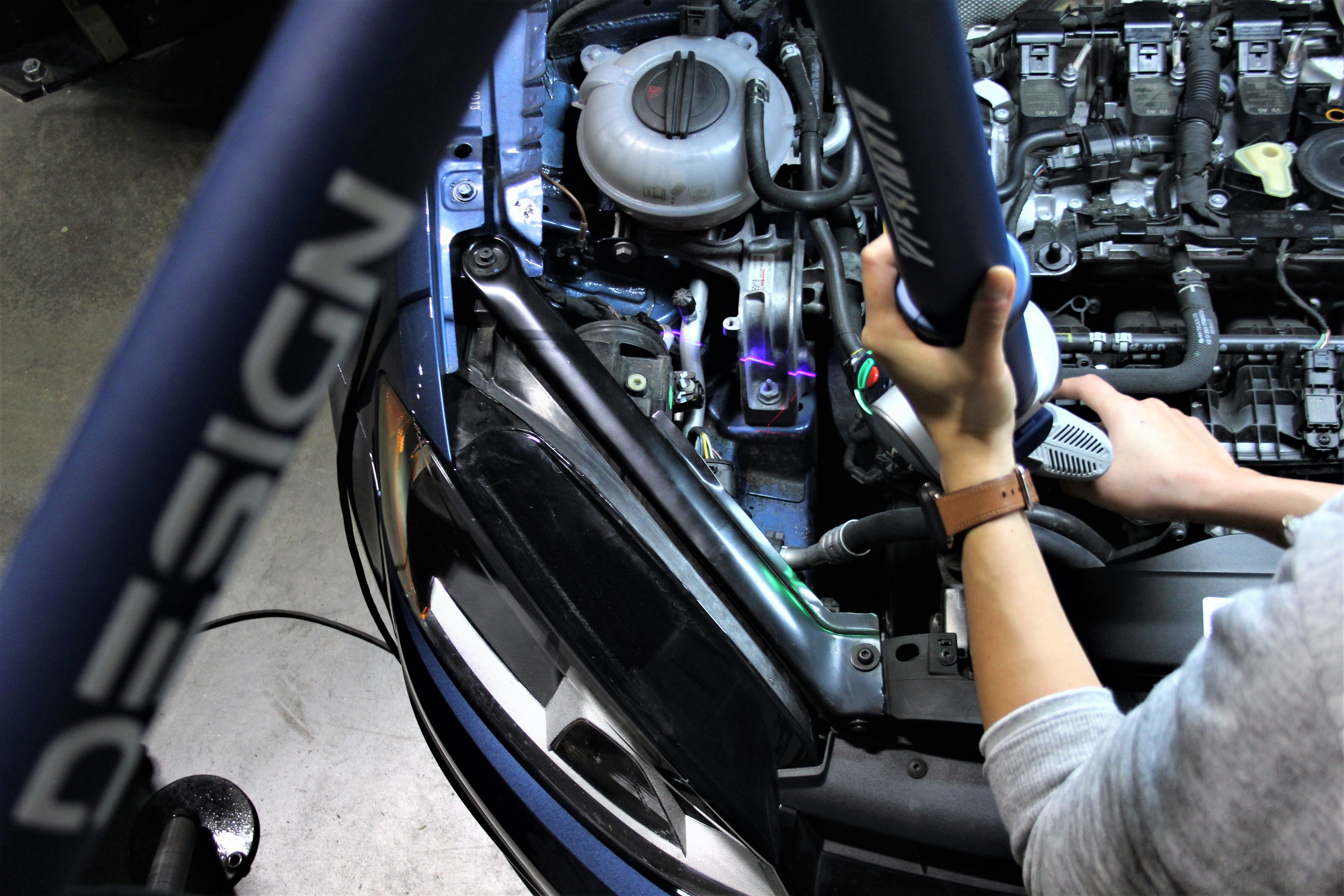
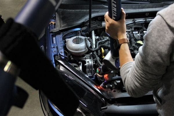
We now have a nifty tool that can literally scan things into a downloadable, digital wireframe of the actual object or space. It uses a laser gun attached to a moveable robotic arm, which "paints" the space in which we want to design. It's like using a spray gun that acts like the scanner found in the always-breaking office printer - but this one doesn't break, and it scans car parts. For each pass made along the area, that image, or scan, gets uploaded through the robotic arm and into a computer, in real time. The result is a digital file that can be uploaded to any computer and then manipulated and used to design anything within the design program's parameters (we use a design suite called SolidWorks®). We went into much more depth about how this tool works in one of our earlier technical articles.
Future!
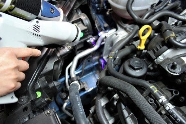
I told you lasers would be involved
Our engineers sometimes have access to files like these before the project even starts, but they aren't too common or even easy to get. Using this robotic arm makes the initial design phase much easier, as the spaces in which we start designing parts become more complex and challenging.
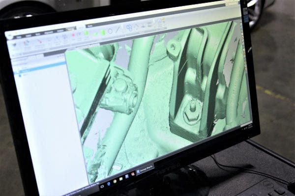
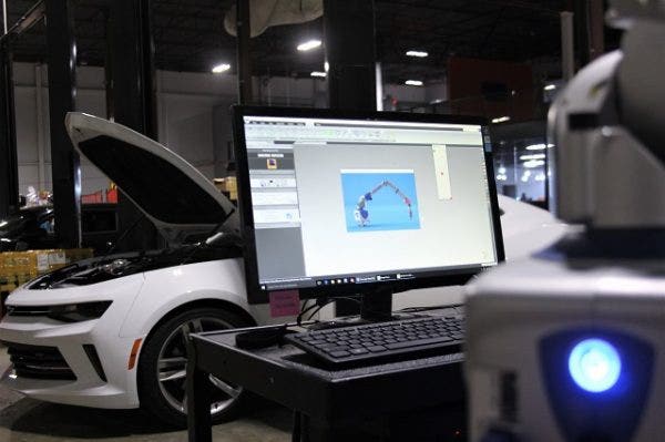
That isn't Microsoft Paint
The above image shows an example of what the arm scans. Neat, right? Our engineers can take this file from the computer in the garage to their desks and then start playing around with some designs. We don't have to worry about any inaccuracies here. If the process is done correctly, there is very little, if any, difference between what is scanned versus the real thing.
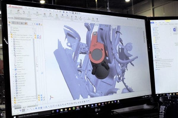
A prototype of the can
Now that we've gathered the necessary data, it's time to design. The above image shows what this design looks like in real time while it is being worked on. I had to awkwardly creep around our engineer's desk to get this shot but I think it was worth it. We are just a hop, skip and a jump away from something we can put on the car, so on to the next cutting-edge tool. To fabricate this bracket, our lead fabricator uses a waterjet. The waterjet shoots a mixture of water and abrasive at over 60,000 psi at metal sheets to cut out whatever shape the designer uploads into the computer. It is then bent to the desired specifications and is ready to go!
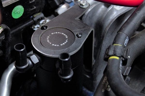
From concept to reality in two steps
The next thing to figure out is routing. This takes a bit of time, but the routing of these lines will be important because they'll need to extend across nearly the entire engine bay. We have tons of hoses in different diameters and lengths for testing, but the task here is to find the optimal combination of those two dimensions. Trust me, it looks easier said than done. We have an idea of how this will work, but testing of this prototype is required before we can just package it up and sell it.
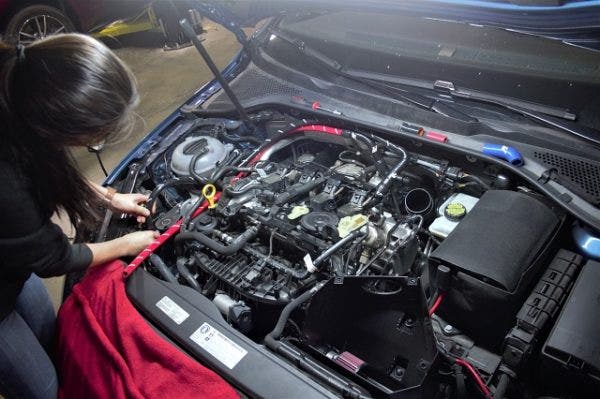
Our engineer working on the line routing
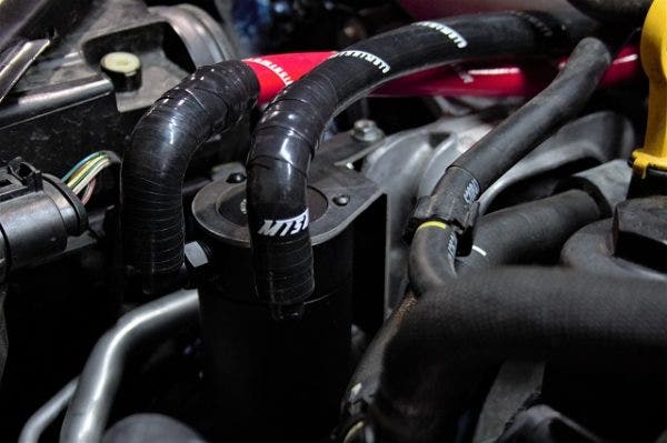
A possible way this kit could be routed
What's Next?
Next, we will go through how we intend to finalize the routing of this kit. The working prototype is currently on our test vehicle and we are putting miles on the prototype so we can see the type of content this catch can collects. We will also walk through how we will adapt these lines to the existing ports. Who knows, we may even have a fully finished prototype that can go right into production by then! Thanks for reading, and stay tuned!
-Diamaan