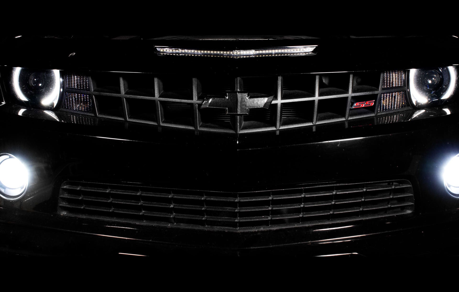
Clean Camaro - Catch Can R&D, Part 1: Prototype Design
Success in engineering is rarely the result of one attempt. Our products go through revision after revision before they ever see the light of day (or darkness of your engine bay). This goes for complex products, like oil cooler systems and intercoolers, to seemingly simple catch can brackets. Our engineers must consider every situation that could occur in a vehicle, then design our products to handle them. The development process for our 5th Gen Camaro SS direct-fit oil catch can is no exception to that rule.
Success is also rarely the product of one person's efforts. Teamwork plays a major role in every product here at Mishimoto. From conception to release, our projects are touched by just about every Mishimoto employee. When it comes to designing and developing a catch can kit, more ideas create a better product. That's why our engineer, Jason, brought in one of our draftsmen, Josh, to help with this kit's design.
This wasn't Josh's first time designing a product, however. In the past, Josh has designed everything from shift knobs to the internal workings of catch cans. He's well versed in our design and engineering processes, making this project a walk in the park for him. Nevertheless, reaching the final product often requires overcoming a few challenges.
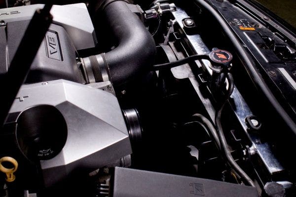
The first step in designing any catch can system is to determine where the can needs to be mounted in order to tap into the PCV/CCV system. The large engine bay of the Camaro is packed with an equally large engine, so catch can mounting locations were limited. Furthermore, the LS3 / L99 PCV ports are located on the passenger side of the engine, right next to the throttle body. Josh decided the best mounting location would either be attached to the accessory belt tensioner bracket or mounted on the passenger side radiator support. With a mounting location decided, the next step was to design the bracket.
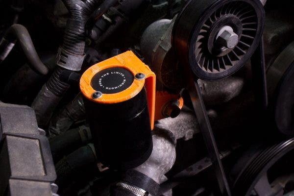
Josh's first bracket design utilized a free bolt on the accessory belt tensioner. The small size meant that little raw material was needed. The mounting position was close to the PCV ports, so the lines could be shorter and less prone to failure. This would all keep the cost of manufacturing down, making the final product cheaper for our customers.
Upon review, however, a couple issues were found with this bracket and mounting location. First, our catch cans weigh the better part of a pound. With that much weight, Josh was worried that the natural vibration of the motor and bumps in the road could lead to cracking in the bracket and issues keeping oil in the bottom of the can. The single mounting bolt also meant that there was a risk of the bracket turning, loosening the tensioner bolt with its rotation. Back to the drawing board.
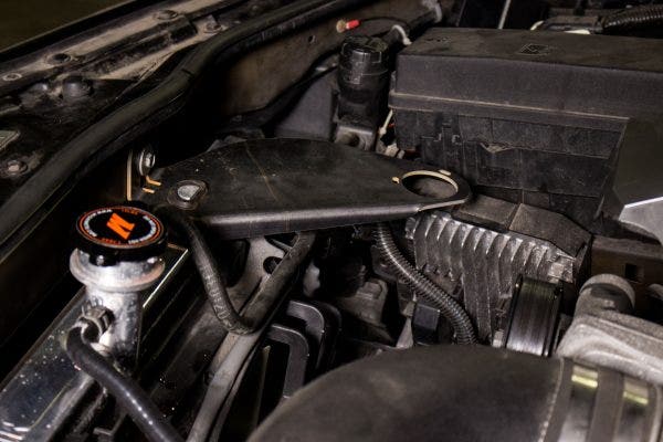
Josh's second bracket made use of the radiator's upper mounting post, replacing the passenger side bracket. A rubber bushing integrated into the bracket isolated the can from vibration and protected the radiator. While the bracket was sturdy and kept the can close to the PCV ports, Josh was not happy with the aesthetics and bulkiness of this design. So, he pushed on.
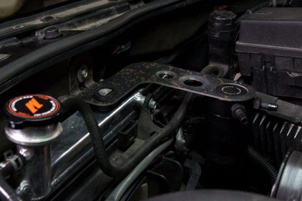
Armed with lessons learned from the previous two brackets, Josh took the best of both designs and created one more bracket. As they say, third time's a charm. This version of the bracket combined the sturdy mounting location of the second bracket with the aesthetics of the first version. Two dimple dies add a little character to the bracket and the rubber bushing on the radiator post isolates the bracket from road vibration and bumps. Another rubber stop on the underside of the bracket provides more support and protection for the radiator. Finally, the long bracket keeps the can close to the engine, making the lines nice and short.
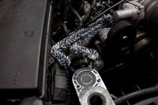
With the bracket design approved, the only puzzle piece left was the routing of the lines. The journey from catch can to engine is pretty short for these lines, but there were a few obstacles to overcome along the way. Josh had to be sure the lines would not come in contact with the accessory belt and would fit behind the throttle body. To mock-up the line routing, Josh turned to our fuzzy engineering friends: pipe cleaners. It may look a little odd, but these pipe cleaners give us a great way to mockup and hold the shape of the lines for 3D scanning or modeling.
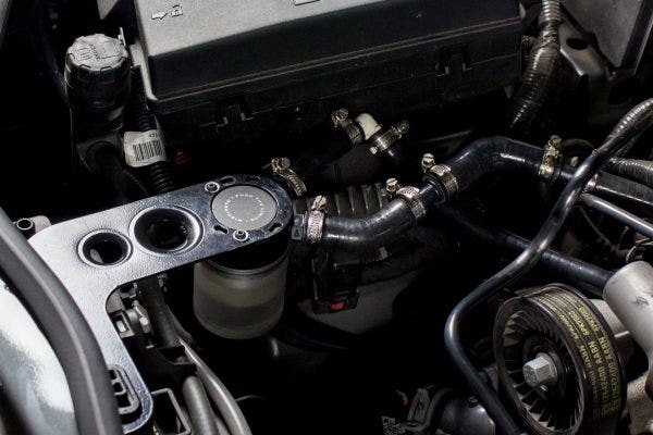
For prototyping and testing, we often assemble connectors and line as needed to fit the determined shape. This gives us a reliable system to begin road testing without having to wait for manufacturing to make full lines. With the lines and fittings assembled, it was time to install the full prototype on the test car and begin road testing. But we faced another challenge before we could start.
Keep an eye out for the next post to see how we overcame the next challenges.
Thanks for reading,
-Steve