In Capable Hands - Transmission Cooler R&D, Part 2: Design
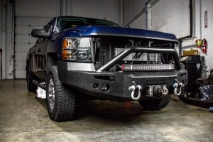
The key to great engineering is often making the most of what you're given"using the resources available to you in the most efficient way possible. When we last talked about the 2011-2014 F-150 transmission cooler, we noted that Ford's engineers left a lot on the table. Behind the grille of the F-150 lays a transmission cooler that's only using about half of the resources given to it. But we're not about to let that extra space go to waste. In this post, our engineer will leverage simplicity and creativity to make the most of what the 2011-2014 F-150 has to give.
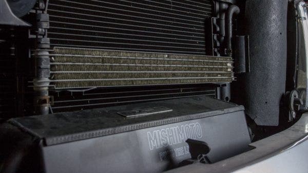
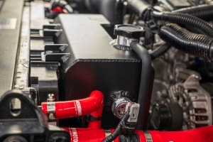
Our design process for this transmission cooler followed the same path it does for most of our products. We started by analyzing the stock trans cooler, some of which you saw in the last post. Aside from noting the overall design of the stock cooler, our engineer also took specific measurements of the surrounding parts for a comprehensive view of where we could improve on the stock design. Many of our measurements focused on the bracket that holds the stock trans cooler in place.
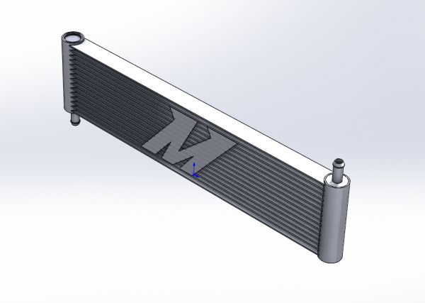
Those measurements allowed us to create a 3D model of our transmission cooler and visualize the improvements. Instead of leaving half the height of the stock bracket unused, our cooler makes the most of every available inch behind the grille. The width of the cooler will remain the same so that we can use the stock bracket and lines. Another key to great engineering is simplicity; the more of the stock components we can use while creating a more efficient cooler, the more bang you get for your buck.
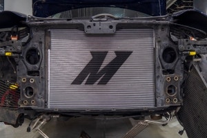
3D models are great for designing and visualizing a part, but the true test is fitting that part on the vehicle. To do that, we fired up our 3D printer and TIG welder and brought our volunteer F-150 back into the shop. We 3D printed our cooler's end tanks and welded together an aluminum bar to act as the core of our prototype. After the epoxy holding the end tanks to the core had cured, we gave it a test fit.
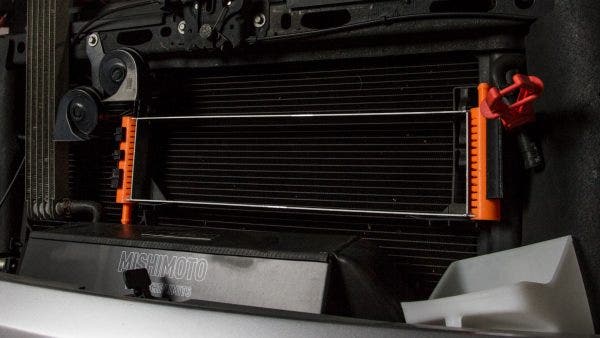
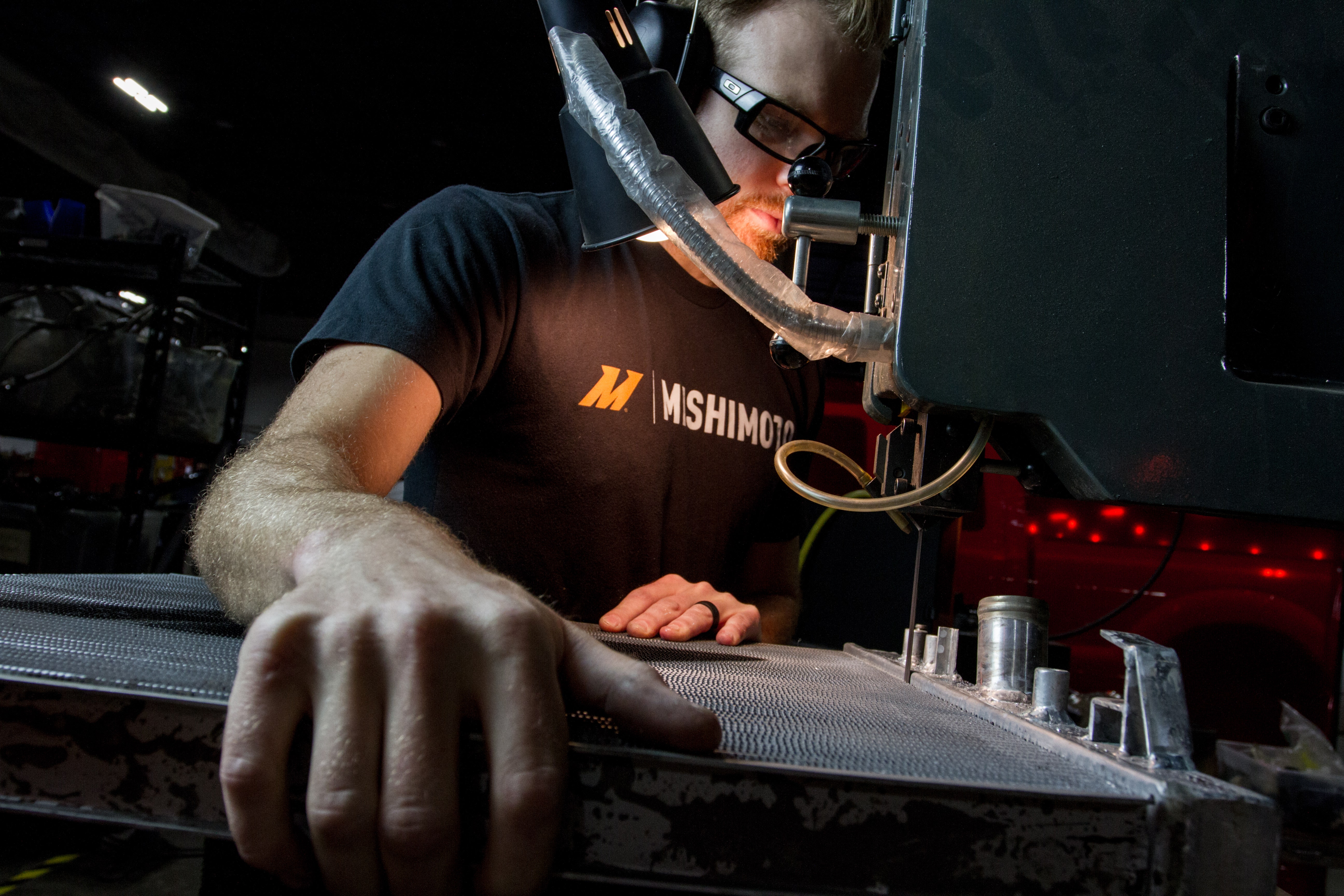
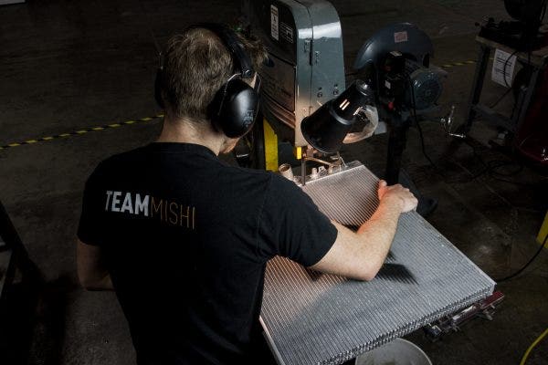
The end tanks clicked into place on the stock brackets and the lines met the ports just right, but there was some concern about the tabs on the bracket pushing against the core of the cooler. We could simply ask the customer to cut the additional tabs off, but then reverting to stock would require purchasing a new mount. That's not something we wanted to put our customers through. So, to see exactly how these tabs interacted with our larger transmission cooler, our engineer got creative. After diving into our stash of disused radiators, he headed over to the bandsaw. We could have just welded in a few metal plates to push against the tabs, but metal plates wouldn't respond the same as tubes and fins. Plus, where's the fun in that?
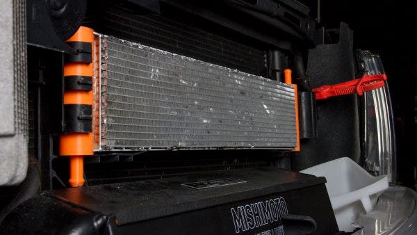
The new core was affixed to the prototype and we test fit it one more time. Our biggest concern was how stable the cooler would be in the mount with the tabs pushing on it. With the prototype snapped into place, we gave the core a shake and pulled it in every direction. Aside from bending the mount back and removing the cooler, it wasn't going anywhere.
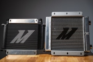
With that, our design phase and prototype test fit are complete. We still have one major decision left to make, however. Our core for this test fit was made from a tube-and-fin radiator, but we want to see how a stacked-plate design will perform. In our next post, we'll dive into testing to see which core style will perform best for our 2011-2014 F-150 transmission cooler. So, keep an eye out for the next update and in the meantime, let us know what you think.