Take in the World - Intake R&D Part 2: Flow Testing
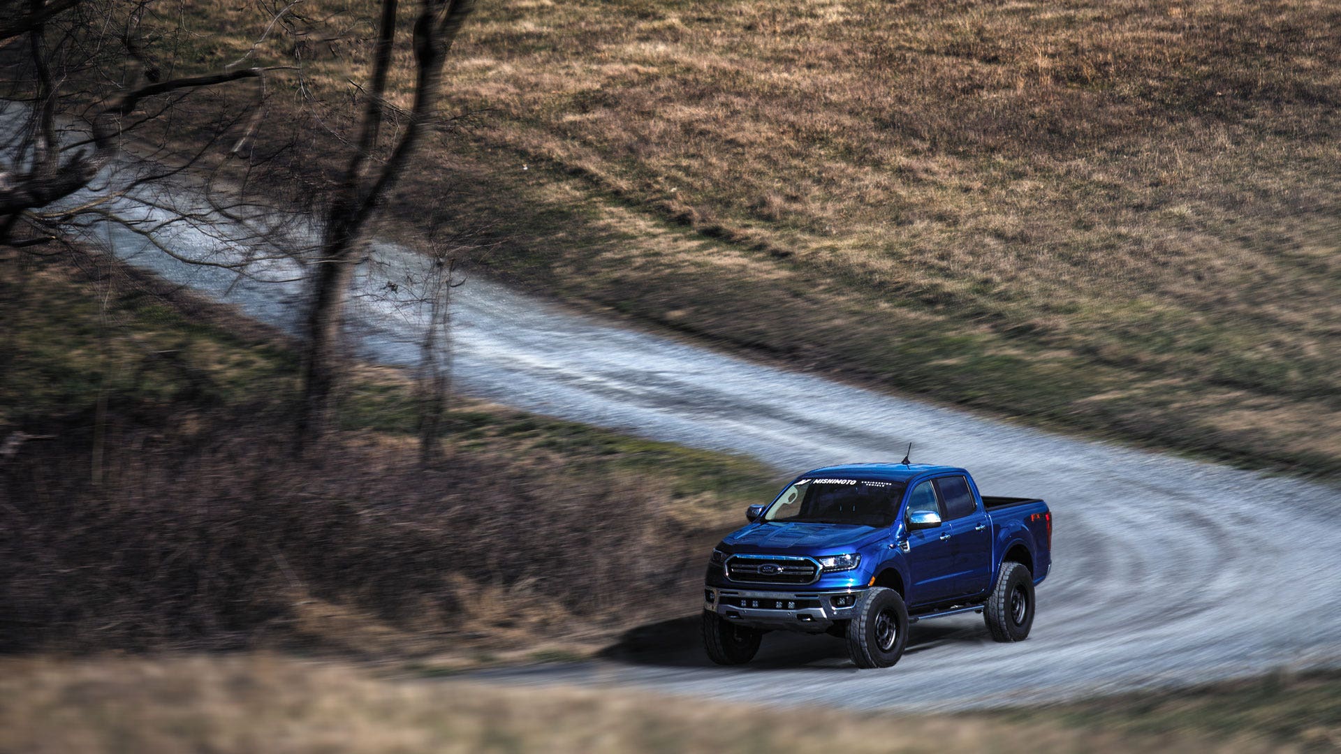
We often talk about how your vehicles are more than just the sum of their parts. Your Ranger isn't about getting from point A to point B with a few bags of mulch in the bed. It's about being able to go anywhere, anytime, and still fit in the garage. The parts under the hood have similar stories. An intercooler isn't just about cooling charge air; it's about letting you spend longer with your right foot on the floor and letting your turbo power your adventures. Radiators don't just cool your engine, they let your truck work as hard as you do. Intakes let you, and your engine, take in more of the world. But even if a vehicle is about more than the sum of its parts, it still pays to look at each of those parts on its own when modifying any vehicle. The 2019+ Ranger's intake might be about taking in the world, but at its core, it's about flow.
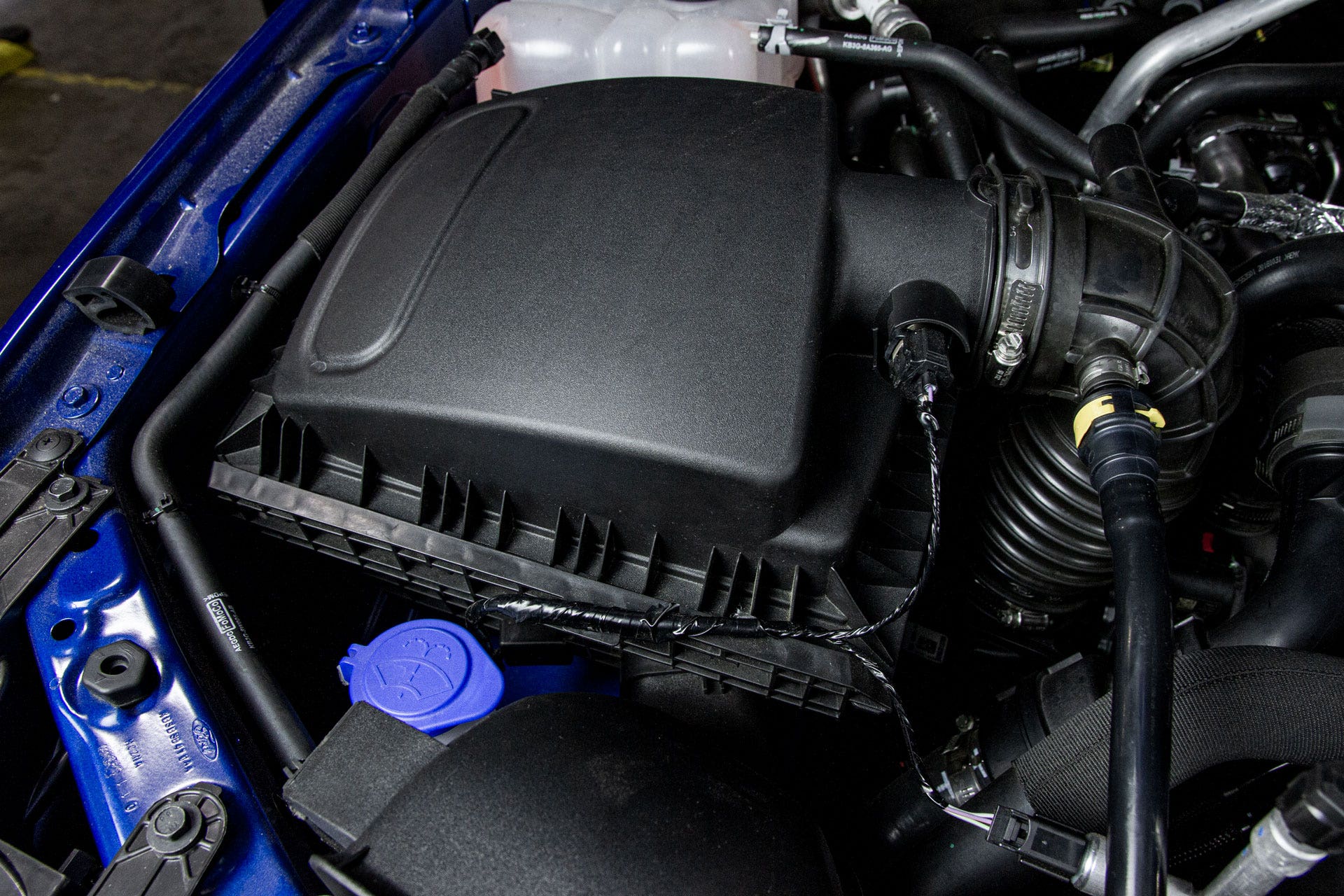
To make the Ranger intake better, we need to know where it stands. To find that out we start by measuring the core of its performance: flow. Our engineer, Ye, began evaluating the stock Ranger intake by removing it from the truck and placing it on our flow bench.

Much like how the Ranger's ECU calculates airflow into the engine, a flow bench measures how much air can move through an object by referencing the pressure and temperature of that airflow. Instead of manifold pressure, however, the flow bench references atmospheric pressure (14.69 PSI at sea level) and the amount of pressure or vacuum needed to generate a specific air velocity. For example, if a part requires 5 inHg of vacuum to flow 500 CFM, it flows twice as well as a part that requires 10 inHg vacuum to flow the same 500 CFM. The results of this test are expressed as pressure drop (inH2O). In the case of a vacuum-operated flow bench, the pressure drop is the difference in pressure between the air at the inlet of the part (atmosphere) and the vacuum that the flow bench produces to pull a set velocity of air. No matter how the machine operates, a lower pressure drop means more flow, and more flow means a better performing intake.

With the stock intake coupled to our flow bench, Ye began testing. We ran the intake through a few different flow rates to see where its overall limits are. At the same time, we used another set of gauges to measure the pressure drop across individual parts. Once we have our prototype intake completed, we'll be able to compare the overall flow of both systems to ensure our intake flows better than stock. But before we can make a prototype intake, we'll use the individual component readings to decide which parts of the intake need to be improved and guide our design.

Our overall flow test revealed that the stock Ranger intake has a pressure drop of only about 1.5 inH2O at 100 CFM of flow; but that pressure drop increases rapidly as more air is pulled through the intake. At 300 CFM, the pressure drop jumped to nearly 10-times that reading, and at 500 CFM the stock intake posed enough restriction to create a pressure drop of over 28 inH2O. Considering even small turbos ingest upwards of 360 CFM to create 15 PSI of boost pressure, the stock intake creates a major roadblock to getting air into your turbo.

Our individual component measurements indicated that the airbox, filter, and the first elbow after the airbox were the most restrictive parts of the stock intake. To be honest, we expected this. Like any other part of the vehicle, the stock filter needs to be durable enough to last between scheduled maintenance, cheap enough to mass manufacture, and effective enough to protect the engine. With the enthusiast in mind, and a little more leeway on the budget, we can produce a much larger, free-flowing filter that still protects the engine and an airbox to suit.
The elbow connecting the airbox to the last section of the intake was the next most restrictive part. Because the airbox is mounted to the truck's body, and the engine can move in the engine bay, the elbow is corrugated to allow it to flex and not tear when the engine thrashes under the hood. This corrugation is almost an inch deep, however, which reduces the volume of the elbow and adds a significant amount of turbulence to the airflow. As the air passes over these grooves, it tumbles and turns around on itself, slowing down as it goes. If we smooth out the elbow and enlarge it, we should be able to increase flow significantly. We'll still need to account for that flex, but we have plans for how to do that elsewhere in the design.

Finally, I'm sure you're asking, "what about the last section of the intake?" While we would love to add even more flow to the intake, touching the last section of the stock intake won't be possible due to the emissions components we identified in the last post. Any changes we make to this section could be seen as tampering with an emissions component. Luckily, we didn't find the last section to be severely detrimental to flow and the upgrades we make to the rest of the intake should free up more than enough flow for even the most aggressive turbo the 2.3L EcoBoost will ever see.

With our flow testing complete we can move on to designing our upgraded intake. In the next post, we'll begin the design process with a 3D model, then bring it to life as a 3D-printed prototype. From there we can test fit and tweak the design to make it perfect. So keep an eye out for the next post and, as always, let us know what you think!
Thanks for reading,
-Steve