Mishimoto Is Dyno-Mite – Dyno Testing Procedures and Data Collection
Dynamometers are the stationary proving ground of the automotive world. These packs and rollers provide us, enthusiasts, with the power figures we need to answer the ever-important question, who’s car is hypothetically faster? While that’s always the burning inquiry on every gearhead’s mind, the Dynapack and DynoJet systems provide much more than bragging rights here at Mishimoto. These instruments provide us with an indoor, virtual test track ideal for gauging what our products will add to your build. But how is that data collected, and how will I know that info is accurate? Well, we’re glad you asked.
In our last post, we covered what dynos we use and how they work. This time around, we’re going to dive into how exactly we used them to deliver precise data on the performance of our products. The underlying thread that pulls all of our steps together is consistency. Consistency is key to ensuring the figures we provide are as accurate to real-world conditions as possible. So with that out of the way, let’s get ready to test.
Preparation
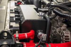
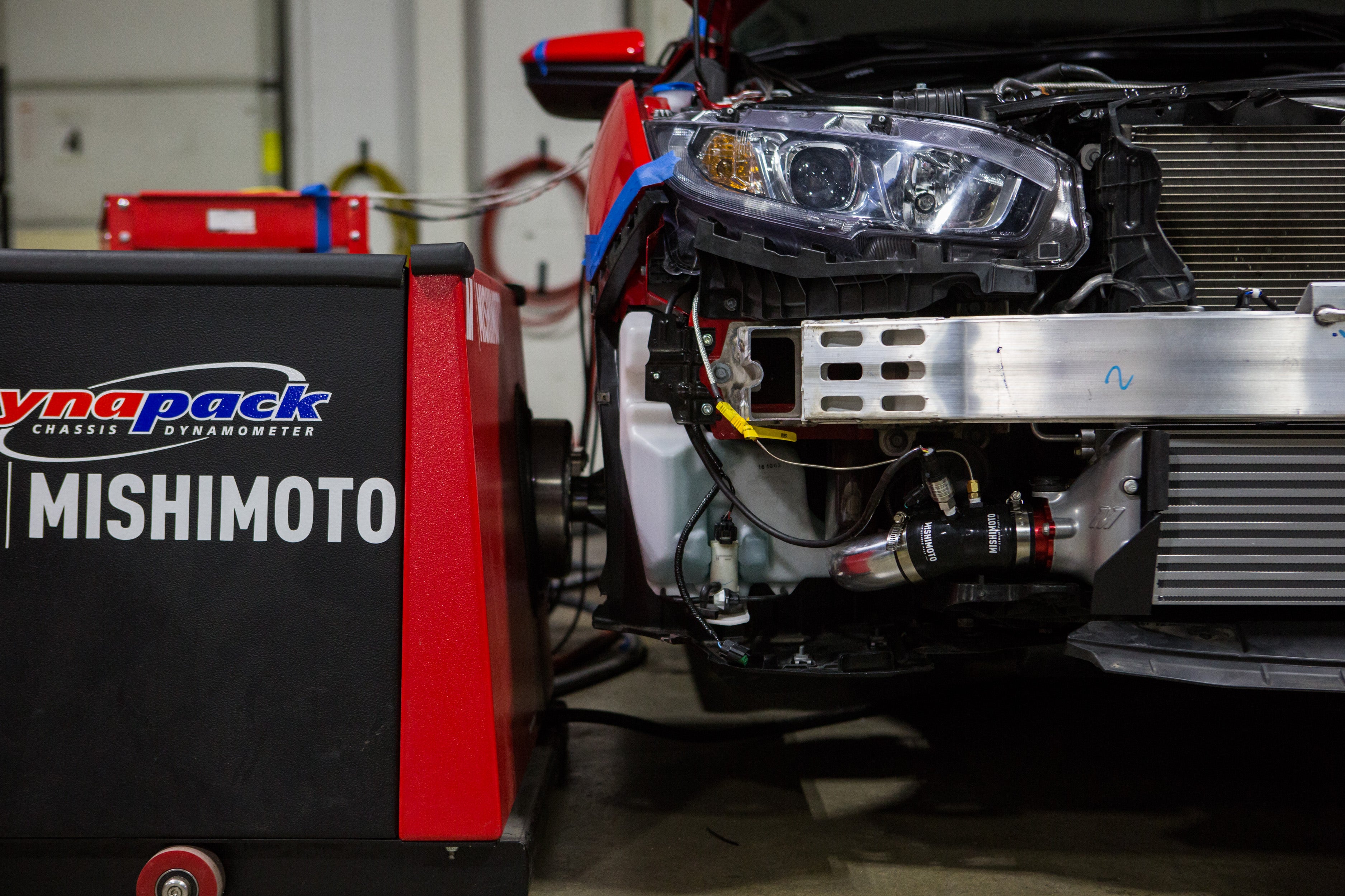
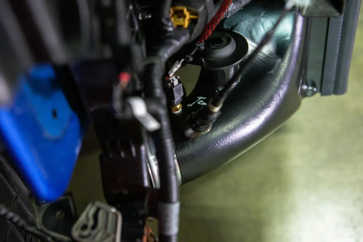
Overall, our preparation is consistent throughout our product line, with some variation to account for our wide range of product testing. In this stage, our engineers have already ensured proper fitment and now start poking holes in our production samples to install sensors. We always install the necessary sensors to collect the core data related to the product, including temperature, flow, and pressure, which all route back to an AEM AQ1 for data logging. In addition to monitoring the main component’s performance, we’re also logging data on adjacent systems. This way, we can determine how our component’s design affects the entire ecosystem under the hood and its primary system. We also closely monitor coolant and oil temperatures in all testing to ensure that we’re not risking the engines of our or donor vehicles.

Sometimes, we need to do more than add sensors to the vehicle. Specifically, the increased air volume can cause sudden changes to a vehicle’s fuel trims when we’re testing intake components. This influx can cause highly inflated power figures after the first installation, which will skew the results of our testing. Of course, a huge boost in power is a great selling point, but in this case, it’s inaccurate, and this figure only temporarily reflects real-world results.

The FK8 Civic Type R is a prime example of a MAF-based vehicle needing plenty of road testing. During the development of our performance intake kit, our engineering team experimented with multiple MAF housing sizes to strike the perfect balance between performance and agreeable fuel trim perimeters. To ensure we hit this equilibrium, we needed to log thousands of miles on our Type R to let the ECU learn and adjust for the increase in air volume without skewing the fuel trims to dangerous levels.
Since we’re searching for the correct power figures rather than just the best ones, we take additional steps to ensure that we’re not testing with inflated fuel trims. Essentially, we drive the car. This gives the ECU the proper time to adjust for the updated intake design and avoid any outliers in the power data. This prep step is typically geared toward MAF-based vehicles, but some speed-density applications also need special treatment. To get a more in-depth look at the difference in tuning, make sure you head over to our other tech blog:
Air Metering 101: MAF vs. Speed Density
Testing Procedures
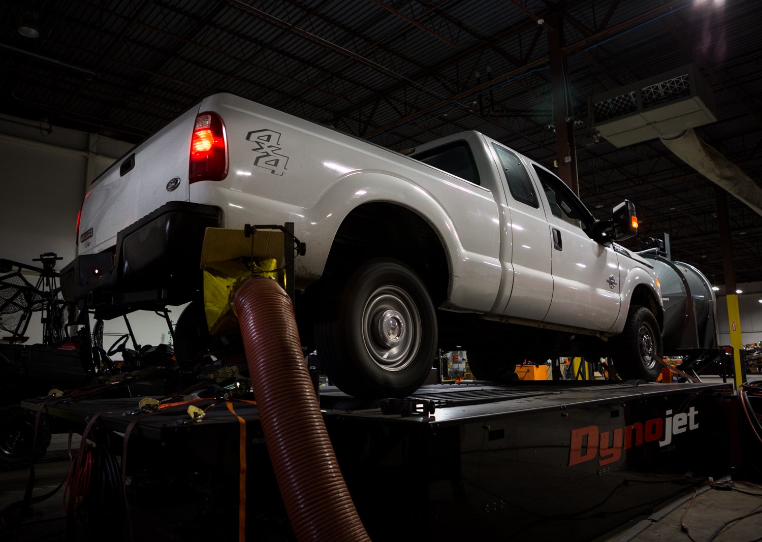
The specific tests we perform on the dyno vary per product category, but we follow strict procedures to ensure that our final figures are as close to real-world results as possible. To start, we kick on our custom-fabricated exhaust extractor and our super-sized dyno fan. For those who have followed along with the blog, you might have seen this fan before. This fan is a retrofitted HVAC fan designed for flowing air through massive office buildings, so it’s ideal for producing simulated real-world wind speeds. After warming the vehicle up to operating temperature, we’ll start with a few shakedown runs. Since some vehicles get a little upset about being strapped down to the dyno, we like to ensure that the vehicle and our array of sensors operate correctly before we start collecting data. Then, once all systems are go, we begin with our product-specific testing.

Power pulls, heat soaks, and simulated load are all means of testing components across the range of our range of products, but they all follow the same philosophy to ensure that our result meets real-world expectations. So now that things are warmed up let’s start with our power pulls.
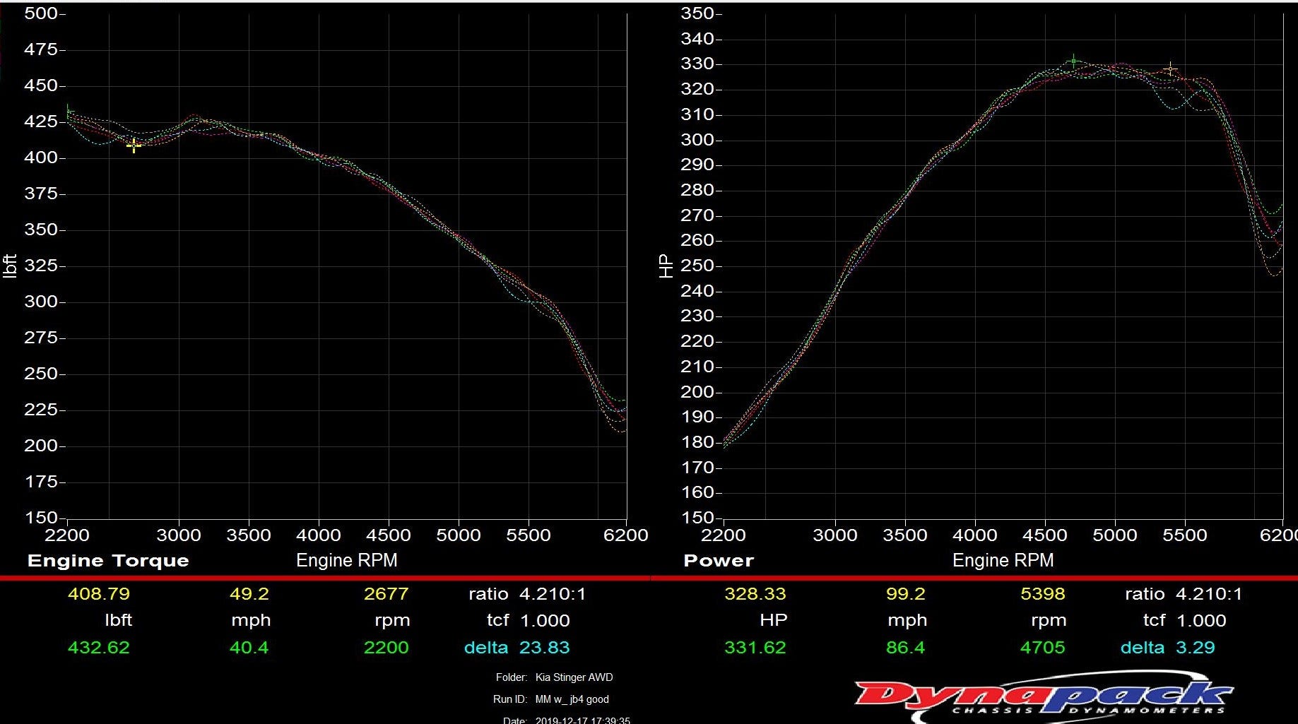
Our engineers see this view when they’re working on dialing in a vehicle. Specifically, this raw data is pulled from our Kia Stinger GT Performance Intercooler development before being refined into our graph template, which you’ll see below. You can see variations between each power pull, but they all fall along the same trend.
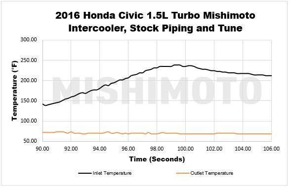
When referencing power pulls, we’re honing in on a singular sweep through the rev range. These curves give insight into how our intake, intercooler, or charge piping performs through the rev range compared to the OEM components. Each pull is run in 4th gear or the closest 1:1 gear ratio, with a proper cool-down period between each test. These singular runs through the rev range are the basis for determining the bulk of our final data for each product, like power figures and heat rejection characteristics. When performing this test, however, it’s more than just two pulls on the dyno with the parts swapped out, and it could even reach upwards of 30-40 repeated tests in the name of accuracy.
Even in our climate-controlled garage, we can still run into variations that give us outliers in the data set. To compensate for this, we repeat the test until we have consistent results between each data set. We’re not necessarily looking to have exactly repeating figures between each run, but data that trends along the same curve for compilation later in the process.

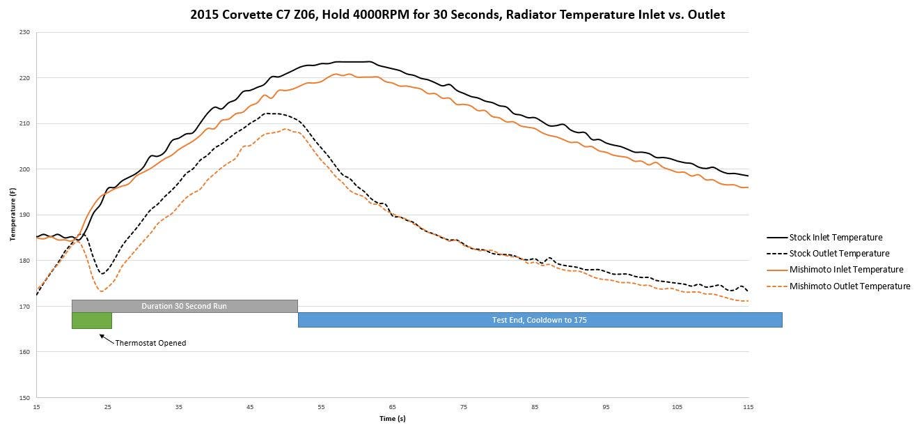
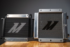
Above is an example of the results of a load test for a radiator. When testing radiators on the dyno, we’re looking at how well the core can cool while under heavy load and dissipate heat once the vehicle is off throttle. In the case of the C6 Corvette, we also loaded a throttle program to simulate a hot lap for a more realistic look into the cooling power of our new design.
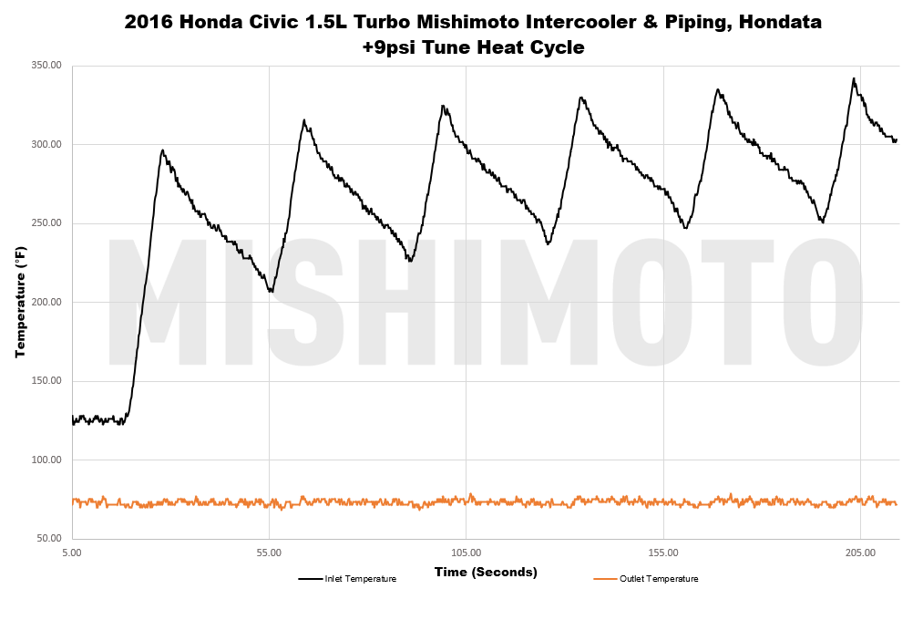
Our process becomes more variable for heat soak and simulated load tests. Both of these tests were devised to simulate the harshest of real-world conditions, which test how effectively our heat exchanger products can repel the effects of heat soak, which entails pushing the test vehicles to their limits. Our heat soak test is most commonly performed on our intercoolers and consists of stacking power pulls back-to-back while forgoing the cool-down period between pulls. The next run starts as soon as the engine returns to idle to build up as much heat as possible. These pulls are repeated up to six times to maximize heat and are only cut short if the stock components or other systems are approaching critical levels.
Our load test is designed for similar purposes but aimed more at our fluid-based coolers. Simulating heavy load is a more optimal way to determine our design’s performance when improving radiators, transmission or oil coolers, or some intercooler applications. Typically we rely on our DynaPack system for this test since the hydraulics can be programmed to apply additional load on the vehicle and put our design under harsher test conditions. Instead of running the vehicle through a series of power pulls, we’re looking to see how well our new design can perform at a certain speed. Our engineer will record the heat rejection data for this test while maintaining a vehicle speed of 60MPH with the additional simulated load. Why 60MPH, you ask? That goes back to our fan. At 12 inches from the front of the vehicle, our fan can produce wind speeds equivalent to the real-world conditions of that speed, so this speed provides the most realistic results.
Data Compilation

The data compilation phase is, admittedly, the least glamorous step in our dyno process. Thanks to our array of data loggers, the most tedious parts of collecting data are automated, but the raw data can still make even the more experienced enthusiast’s head spin. So, to make the results easy to view, our engineers still have some work to do.

Our number-crunching process starts from the driver’s seat of our test vehicle while it’s still strapped to the dyno. Since our goal is to deliver real-world improvement results, our engineers must ensure that the captured live data reflects that outcome. If our results have wildly inflated outliers or are way below the trend, we’ll either omit those tests or start a new data set. We commonly spend days or even weeks on the dyno to lock in a consistent set of results. Once the engineer is satisfied with the data set, then we hit the spreadsheets.
Even after running the vehicle dozens of times on the dyno, we still need to narrow our final graphs down to a single set of results for that easily discernable difference between each component. Our engineers have a known starting point since they’re reviewing their data as it’s collected, but there’s still plenty of sifting to do in the name of thoroughness. Our engineering team sifts through their selected data set on the hunt for the most realistic result. Since we’re striving for accuracy, we’re not looking to pluck out the results that show the best improvement but rather the graphs that portray what our customers will most likely experience after installing our products. With the optimal test result selected, organizing our final charts is as simple as plotting the raw data in our template for a clean and easy read of the results, as seen in the graphs above.
No matter the vehicle making its way to the test area, dyno days here at Mishimoto are met with the buzz of excited curiosity. The theoretical proving grounds are in effect as we eagerly await the final power figures. For our engineering team, the end goal is much more than bragging rights. We utilize these packs and rollers as a tool to prove our design concepts through meticulous testing. However, more times than not, this attention to testing procedure detail delivered accurate and consistent bragging rights.
Thanks for Reading!
-Nick