"The TurboChevy" - Intake R&D, Part 2: Weighing Our Options
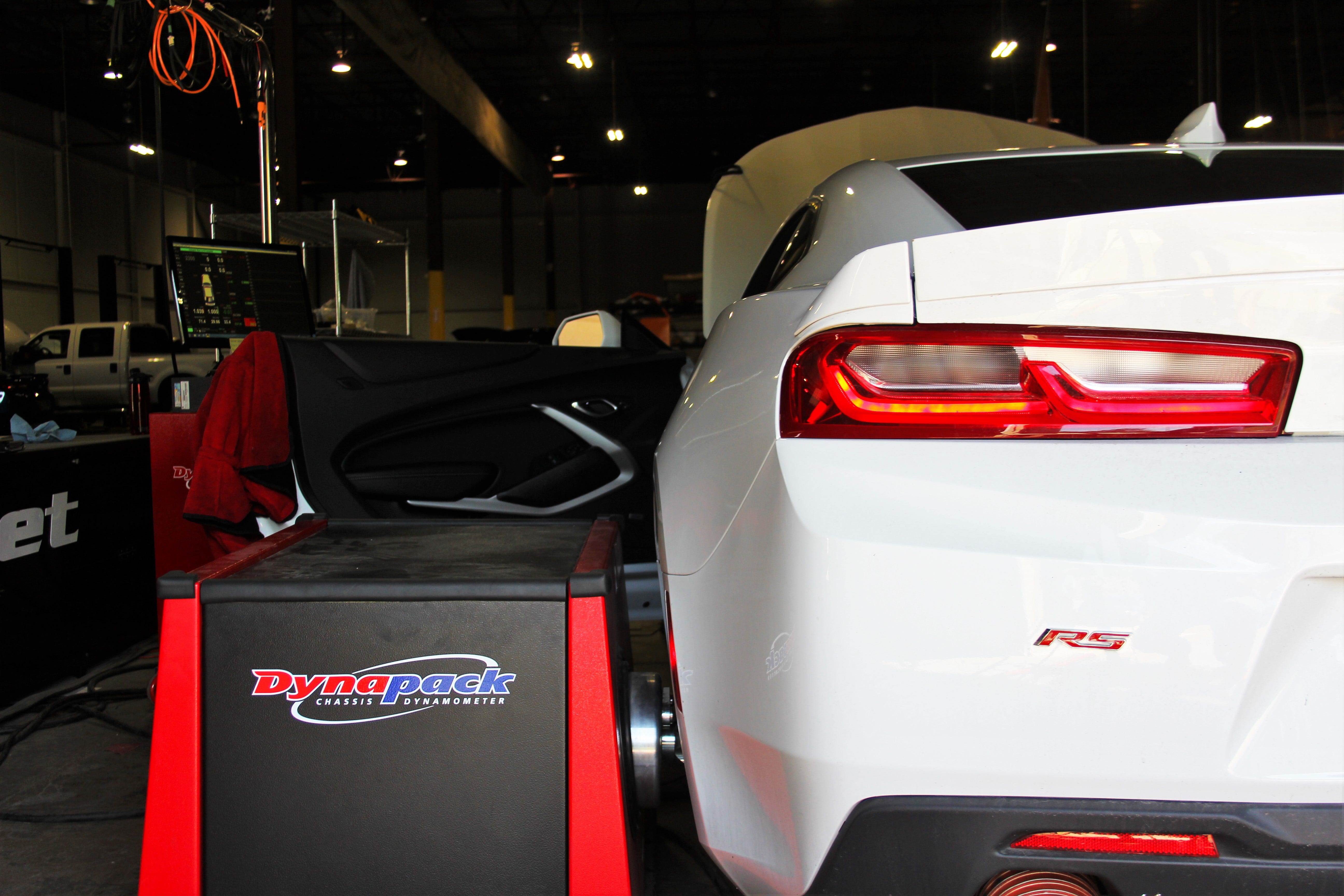
The team developing this intake for our 2016 Chevy Camaro 2.0T or what I call "The TurboChevy" has been buzzing with activity. In the last post, we discussed the stock intake and analyzed each component to get a good understanding of its design. There were several ways our engineers could have created an intake for this system, and we tried and tested a few of those designs, which yielded some interesting results.
If you followed our 2016+ Camaro SS intake development, you'd see that we went through multiple designs to achieve the desirable. In some ways this project is similar; let's walk through what we found!
Camaro parts under inspection
The Decision 2016
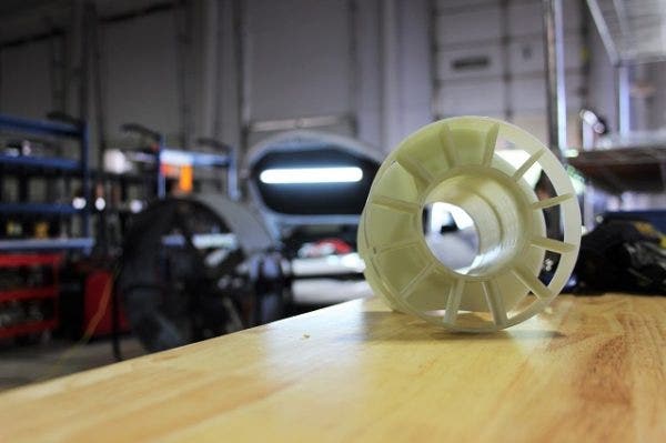
Rather than assume that the turbo muffling piece is actually a restrictor, we wanted to test it to be sure. Two models were 3D printed: an elbow designed to include the muffler, and an elbow that attached directly to the turbocharger, omitting the muffler. We tested both on the same day.
Camaro performance parts up for testing

Camaro performance parts up for testing
For the first test, we used the elbow that included the muffler piece, and the results were fairly impressive. Although the air still gets trapped in the muffler housing before it hits the turbo, the intake tube itself has more volumetric area, theoretically compensating for any performance impedance from the muffler. We saw even better results when we tested the system without the muffler piece.
Now here is where it gets interesting. The next two prototype designs yielded some amazing gains, but we saw an odd polarity in their performances.

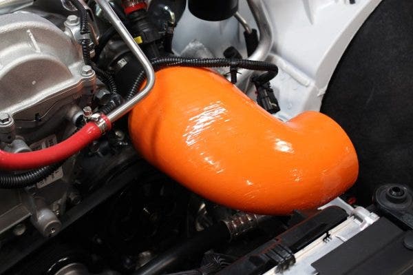
Prototype intake with a 90˚ bend in the pipe
The original version of the intake that attached directly to the turbo had a 90˚ bend in the pipe right after the filter, as you can see above. Some people say this type of design should usually be avoided because airflow velocity slows down dramatically and becomes inconsistent when passing through a sharp bend. The inconsistencies begin right at the bend, because the airflow streaming towards the outside of the bend will have much more velocity than the airflow streaming towards the inside of the bend. However, in this case, there is a straight section after that bend that is long enough for the airflow to counteract any negative impacts on performance from this type of bent design. Of course, this depends on the vehicle and engine application, and considering this TurboChevy has a pretty sharp bend in its stock design, it was worth giving it a try.
Prototype with 90˚ bend
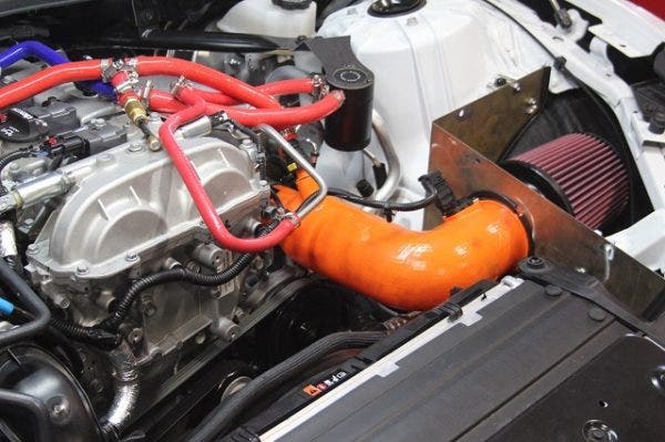
This first design yielded some great gains, but we didn't want to jump to conclusions until we tested another design. The second elbow design is similar, but with a 50˚ bend instead of having a 90˚ bend.

Prototype with 50˚ bend
This second design did much better with our testing. It did not make as much power, but it flowed better, and that came as a bit of a surprise. Usually, the intake hose that has better airflow yields better gains, but that wasn't the case here. Either way, our engineers decided to go with the second design as it would be better for the car in the long run. More on that in a bit.
It's Decided, Now What?
The prototype seen above was intended only for quick dyno-testing, so it wasn't suitable for the road. The mass airflow (MAF) housing and the intake elbow needed to be constructed of something more durable than the 3D printed material.

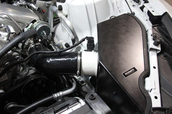
Updated prototype
This was as close as we're going to get to a production sample, and everything came out great! The intake hose was made in-house from scratch, and the MAF housing was specially made of a porcelain that is resistant to high temperature. Now that we have a final design that we can use for extensive testing, how about some video and data?

Camaro 2.0T performance intake dyno results

Camaro 2.0T performance intake AFR results
Power output went up, with the max gains hitting 21 hp and 18 ft-lbs of torque. Peak gains were at 12 hp and 5 ft-lbs - pretty decent gains! These are the results after about 700 miles of road testing, so the engine's computer learned well and adjusted to the change in airflow. This is a more accurate representation of the real-world performance of intake. It is important to let the car adjust a newly installed intake before making any power claims, because the initially reported numbers could change later on down the road. It is also important to monitor the air-fuel ratios, which would show whether the car would be safe to run on a stock tune.
Road testing is especially important for aftermarket intakes. Before we let the car learn itself during those 700 miles, we saw gains of 40+ hp. It's important to note that without letting this car go through the proper learning process, gains like these are essentially artificial. When we saw these huge numbers, we could have easily called it a day and released this beauty right then and there for presale, however, that isn't what Mishimoto is all about. We want to test, test, test before you get our products, so we can be as sure as possible that you are getting the best.

Our prototype on the flow bench
We measured the pressure drop in our Mishimoto prototype vs. the stock intake as well. Check out the graph below.

Flow bench testing data
We calculated this pressure drop by using simulated yet constant real-world driving conditions. These data points were gathered at 1,000 rpm increments, starting at 1,500 rpm. Boost pressure and ambient temperature were among the many variables we used to get these calculations, and we had to be sure that these things stayed constant. Keep in mind that this was a fully simulated test run, but it should give you an idea of what our kit can do with respect to airflow. According to our graph, we see a pressure drop of about 40%, which is great news for how this intake handles airflow.
What's Next?
With our data finally in, we are satisfied with our results, so we have kicked off production. Once we get a production sample into our R&D facility, we'll show everyone what it looks like. For now, let us just take in how awesome our in-house design looks!
The final version of the prototype!
Thanks for reading!
-Diamaan