BMW N55 Direct-Fit Catch Can R&D, Part 2: Protect What Matters Most
You spend hours washing, waxing, and polishing. Not a single drop of water or speck of dirt is left on the paint's surface when you're done. The interior is the same story; the carpet, seats, and dash look better than on the day you picked up your new BMW from the dealer. You spend precious time and effort protecting your investment from the outside, but what about the places you can't see? I don't mean that spot under the seat where you have to break every bone in your hand to retrieve your phone. I mean the heart of the car: the engine. Using high-quality fuel is a start to keeping your engine healthy, but there are more threats that you may never see coming until they've already gotten the best of your engine.
Looking Back
In the last post, we looked at the N55's stock PCV system; we examined its advantages and disadvantages, and how blow-by can harm your engine. We also took a quick look at how we started developing our catch can. This time, we'll be taking a look at the prototype system we've created.
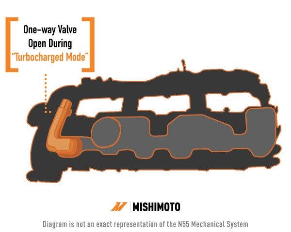
The N55's valve cover. The orange highlighted area shows the check valve that is open during "turbocharged mode" and the tube that leads to the turbo inlet pipe.
Before we dive in, let's take a minute to recap what we discovered in the last post. The N55's PCV system is one of the most complex systems we've looked at here at Mishimoto. Because the N55 is a turbocharged motor, its PCV system operates in two different modes: turbocharged and naturally aspirated. These two modes route blow-by into two separate sections of the intake tract. In turbocharged mode, the blow-by is introduced into the intake upstream of the turbo, resulting in more of the intake system (including the turbocharger) being exposed to unburned oil and fuel.
Decisions, Decisions
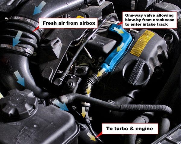
The N55's PCV system operating in turbocharged mode. The blue highlighted area shows the one-way valve that allows blow-by into the intake track before the turbo.
For this catch-can kit, we decided to target the turbocharged side of the N55's PCV system. The increased exposure of the intake tract makes this the ideal location to install a catch can. Also, because cylinder pressures are higher under boost, even more blow-by is created in turbocharged mode.
To start developing our catch-can kit, we first had to decide where to mount the catch can itself. We didn't have much of a choice; BMW really crammed the N55 into the engine bay. There is some room on the driver's side behind the headlight and around the strut tower. However, that would require routing lines halfway across the engine bay, and we wanted this kit to fit the stealthy, unassuming feel of the 135i and 335i. Also, there's no way to route the lines under the engine cover from this side.
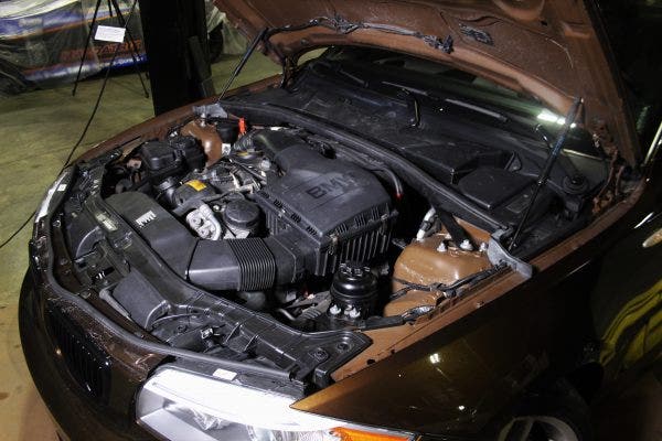
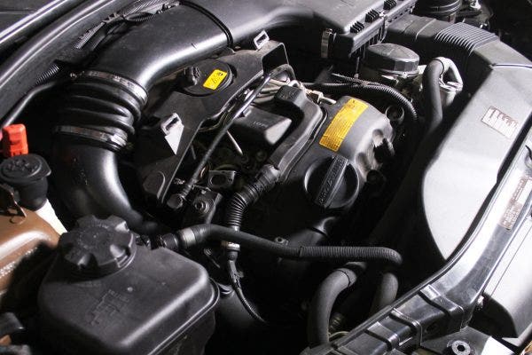
The driver side of the BMW 135i engine bay.
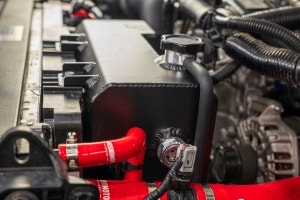
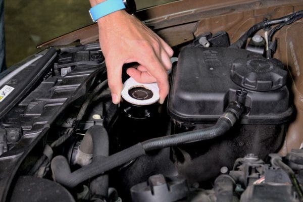
Space on the passenger side of the engine bay is more limited but presents the shortest route to the PCV system. We decided that the best spot for our catch can would be right next to the coolant reservoir. This position will tuck the catch can tightly into the corner of the bay and allow the lines to run underneath the engine cover, no cutting required. Once we decided on this position, our engineer, Jason, took some measurements and cut a cardboard bracket.
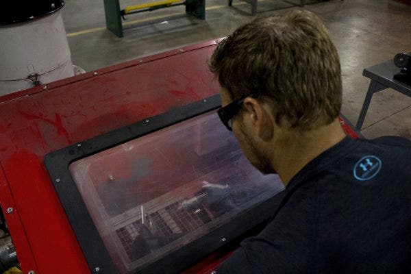
Jason test-fits the cardboard bracket before cutting a metal version on the waterjet.
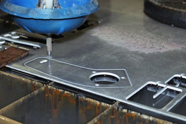
After checking the fit, Jason turned his paper template into a 3D model, added a few bends, and sent it over to our fabricator, Mike, who cut it out on the waterjet. After the waterjet had done its thing, Jason decided that the bracket needed a little flare. Some drilling and a dimple-die later, we had a pretty cool-looking prototype bracket.

Jason adding some style to our prototype bracket with a dimple die on the press.
Pesky Little Heater
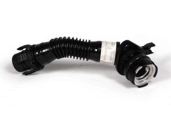
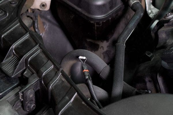
The N55's PCV heater and hose.
After we finished the prototype bracket, we moved on to routing our lines and connecting them to the PCV system. For the inlet side of the catch can, this wasn't too difficult. The valve cover on the N55 contains a built-in PCV valve that connects to the turbo-inlet pipe with a detachable tube. On the valve-cover side, this tube simply slides into a fitting on the valve cover and clips into place. This allows us to match the diameter of the tubing and simply slide the catch-can line onto the fitting.
The outlet side of the catch can was a bit of a challenge, however. Instead of a clip-on fitting, this side of the PCV tube contains a heater element that screws into the turbo-inlet pipe. This heater element is essentially like the cigarette lighter in your car and helps to keep any fuel and oil vapors from condensing in the intake.
Here you can see the heater and hose connected to the valve cover and turbo-inlet pipe.
One solution for this issue could have been to unplug the heater and simply mill an adapter to screw into the turbo-inlet pipe. However, if the heater were left unplugged, it would inevitably throw a check-engine light, so that idea was quickly discarded. Another option could be to use a similar adapter, but keep the heater plugged in and tucked out of the way in the engine bay. While this solution would prevent a check-engine light, we're not so keen on having a hot heater element dangling under the hood.
This left us with two options: Trick the car into thinking that the heater was still plugged in, or find a way to connect the catch-can lines to the heater itself. The first solution would require fabricating an adapter with an integrated electrical connector and resistor. The N55's computer simply checks for resistance across the two wires to ensure that the heater is working. All we would have to do is match the resistance of the heater element, and the computer wouldn't know the difference, so we gave it a shot.
Our chosen resistor inserted into the PCV heater's harness for testing.
We started by measuring the heater's natural resistance, hoping that it wouldn't change as it heated up. From there, we found a resistor to match what we measured, and we simply plugged it into the car's connector. It worked! " sort of.
One worry we had, before even trying this, was heat. Resistors work by converting electrical energy into thermal energy; essentially, the heater element that we removed functioned as a big resistor. We weren't sure how much heat would be generated by the actual resistor, but once we started the car, we learned pretty quickly. Within seconds, the resistor was way too hot to touch. Back to the drawing board.
With only one option remaining, we sought to find a way to connect the catch-can outlet to the heater itself. We had a hunch that what was underneath the tubing on the heater would be similar to the valve-cover side of the PCV system. Manufacturers like to utilize a common design for components that share similar functions, because it cuts down on tooling costs and manufacturing times. So, it's often safe to say that what's on one side of a tube will be mirrored on the other side.
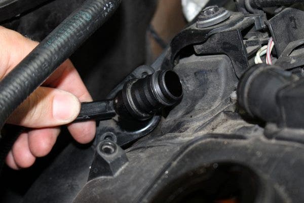
Here you can see the PCV heater in Jason's hand. With the hose removed it is much easier to attach a hose for our catch can.
With the help of a heat gun, we took a few minutes to remove the tubing from the heater and found that we were correct! This process could easily be repeated with a hair dryer at home. Underneath the corrugated tubing (that was already cracked after only about 30,000 miles, I might add), we found a fitting that was similar to the valve-cover side of the PCV system. We were then able to slip our catch-can line over this fitting for a perfect seal.
Finishing Touches
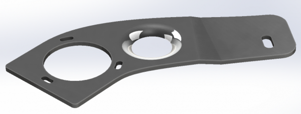
The final 3D model of our catch can bracket.
The final task was to route the lines underneath the engine cover for a stealthy, cut-free look. Jason whipped together some connectors and tubing. While it may not be the prettiest prototype, Jason ensured that the system was leak-free so we could begin testing. You may also notice that we are not using our typical shiny silicone hoses here. While silicone offers greater durability than most other materials, we wanted to stay away from components that would stand out too much in the engine bay.
Jason sandblasting the N55 catch can bracket.
After all the lines were routed, Jason created one more 3D model of the bracket for a cleaner look. After cutting it out on the waterjet, he gave it a quick sandblasting and a coat of paint before assembling it with the full kit on the car. The final product is definitely stealthy and, to the untrained eye, looks damn-near factory. Check it out!
Our N55 catch can prototype stealthily lurking in the corner of the 135i's engine bay.
Coming up
Now that we have a functional prototype, we're on to testing and modeling in preparation for production samples. This donor car will be going back to its loving owner for a few thousand miles before we check out what our catch can has gathered. In the meantime, feel free to leave any feedback, comments, or questions!
Thanks for reading!
-Steve