A Cooler for Atlas - Transmission Cooler R&D, Part 2: Prototype
From the outside, you wouldn't think that the modern pickup truck is exactly the evolution of Henry Ford's Model T. Under the surface however, you might find that the two are more related than they appear. The Model T was a car, built for the masses, designed to be affordable, approachable, and to get people where they wanted to go.
It didn't take long for Ford and other manufacturers to realize the potential of an affordable utility vehicle. A vehicle that helped them work, so that they could afford to go places in their car. Pickups have grown to sell almost twice as well as cars since the Model T "Runabout" was introduced in 1925, and it's hard to find a vehicle that can do as much as a pickup. For all the development that has happened in nearly a century, the pickup could still use some improvement to make it a better workhorse.
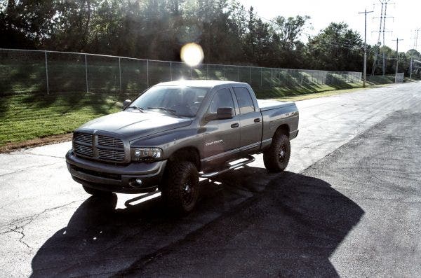
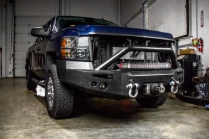
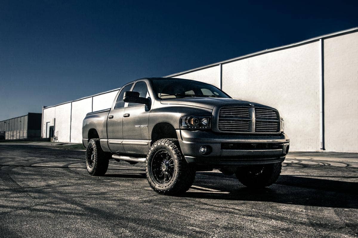
One of the most worthwhile improvements, in the case of the 2003-2009 Dodge Ram 2500/3500, lies in the transmission cooler. Pickups have become incredibly powerful vehicles (like supercar powerful), and the loads they haul would astound the original owners of Model T Runabouts. That power and weight puts a massive strain on the truck's transmission and, as we saw in the last post, the stock transmission cooler often can't keep up. That's why we've been hard at work building a transmission cooler more suited for the stress your truck goes through.
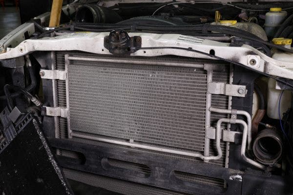
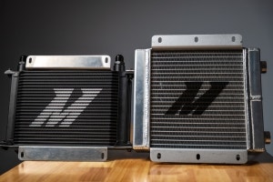
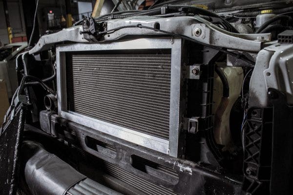
When we looked at this project last, we knew that the transmission cooler needed to be upgraded, but we didn't quite know how. The stock cooler is already large, taking up almost all the space between the bumper beam and the rad support. But, "almost all" is not the same as "all," and there's room to increase the core size. Adding to the width of the core wouldn't be a problem, essentially requiring shorter brackets and a rework of the line connections. To add to the height of the cooler, however, a few more complicated adjustments were necessary.
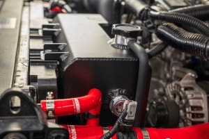
The thermostat block would need to be redesigned to work with our thermostat and fit within the new design. With the core size maximized, the new cooler will have a 159% larger surface area to aid in pulling heat from the fluid passing through the cooler. Surface area is especially important in this case because the transmission cooler is sandwiched between the radiator and intercooler, limiting airflow.
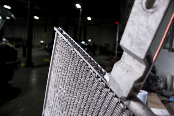
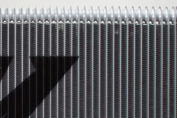
Making the cooler larger was a good start, but, as all the pretty girls in high school told me right before they dumped me, it's what's on the inside that really counts. These trucks see some abuse, so our cooler needs to squeeze as much efficiency into the useable space as possible. To do that, we needed to see what was going on inside the stock tube-and-fin cooler. A quick trip to the bandsaw revealed the inner workings of the stock cooler. Inside, we found strutted tubes, which give the core more strength and rigidity. However, we also found that the tubes lacked any turbulators. Given these findings, we knew what needed to be done.
Our cooler will ditch the tube-and-fin construction in favor of a stacked-plate design. While the stacked-plate cooler may look similar to the tube-and-fin cooler, there are a couple key features that differentiate the two. Aside from being stronger thanks to the thick plate walls, the stacked-plate design will also be more efficient. Instead of the fluid flowing along the length of the cooler, our design will rotate the plates 90 degrees to flow the fluid along the vertical axis. This will let us cram more plates into the allotted space.
The plates will also be shorter than if they ran horizontally across the core. That may sound like a detriment to performance, but the shorter length means that every inch of plate is being used to cool fluid and no space is wasted storing already cooled fluid. But, as we pointed out earlier, it's not just the size of the cooler that matters.
You may have noticed a strange word in the review of the stock cooler internals: "turbulators". It sounds like a made-up word one would use to convince their significant other that they need to buy more parts, but it's a very real and important concept in fluid coolers. In a liquid-to-air cooler, the most effective portions of the cooler are those exposed to fresh air. Typically, the front of the cooler is far more effective than the back. As the air flowing over the core heats up, it loses its ability to pull heat from the cooler. That means that fluid touching the front of the tubes is cooled more effectively than fluid touching the back of the tubes.
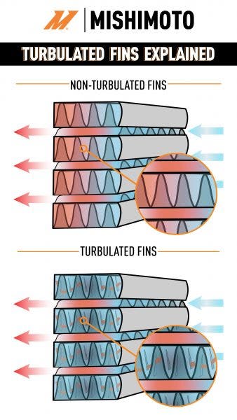
This diagram shows how turbulators move fluid across the tube, ensuring that all of it is cooled evenly.
Many coolers employ turbulators to overcome that difference in efficiency. The turbulators move the fluid from the back of the tube to the front as it flows through the cooler. As the fluids moves, more of it is exposed to the effective areas of the tube. Looking at the diagram above, you can see that the fluid in the tubes without turbulators is cool at the front, and hot at the back. On the other hand, the turbulated fins in the lower diagram move the fluid throughout the tube in both directions, cooling more of it.
The stock Ram trans cooler does not have turbulators, so the fluid flows from one side of the core to the other, with only a portion of the fluid ever contacting the front of the tube. Our cooler's plates will use turbulators to make sure every ounce of fluid is effectively cooled.
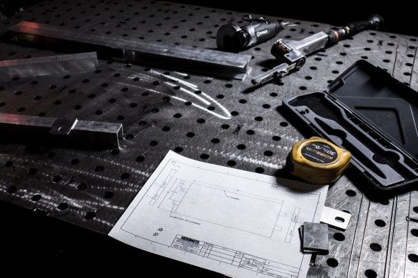
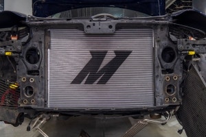
With all the planning and designing out of the way, it was time to start putting pen to paper and welder to metal. Measurements and a drawing in hand, our fabricator grabbed his welder and got to work. Before a production sample could be started, a prototype was needed to verify that our design would fit and that the mounting brackets were spot on. To create that prototype, u-channel aluminum bars were welded together to represent the outer perimeter of the cooler.
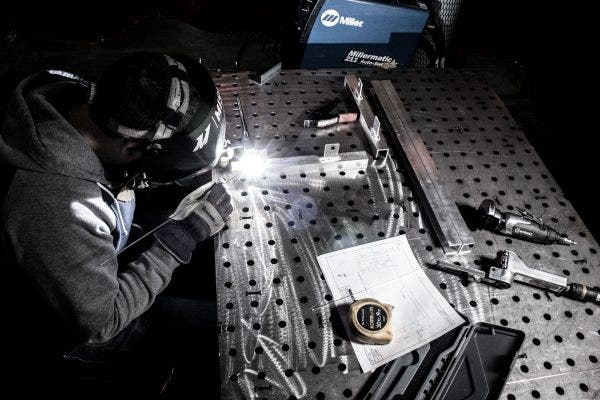
On the ends of the prototype, brackets were measured out and welded solidly in place. Once the welds had cooled, we bolted the massive aluminum box to the truck. The proof of concept was complete, and we had what we needed to move forward with production samples. Our drafters drew up the final designs and sent them off to manufacturing. All we could do now was wait.
Thanks for reading,
-Steve