Help Me Ronda, Help Me Get 'er Outta My Intake - Catch Can R&D, Part 2: Testing for Blow-by
Last time, in the first Camaro 2.0T catch can R&D post, we learned a little bit about blow-by, the CCV system, and how a catch can serves to prolong the life of your Camaro. If you need a refresher, we have a technical article all about why blow-by is terrible for your engine. We left off with Steve setting up his testing rig, but I want to go into a bit more detail on what exactly we wanted to test.
Test Prep
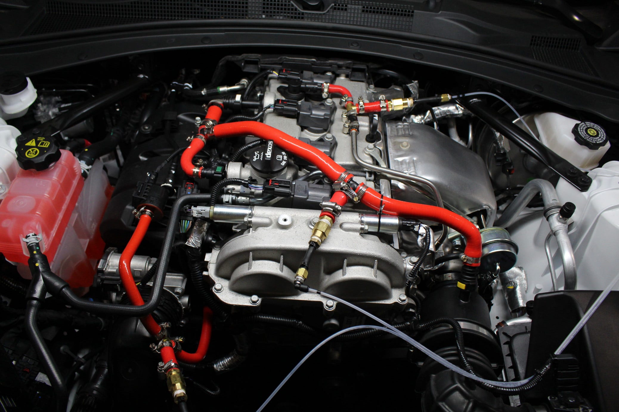
As we discovered in the first post, the OEM system appears to have three different CCV valves. On further investigation, we found that these three valves comprise two separate systems. One system features two CCV valves on the valve cover that connect at a T-joint and run to the intake. The other system connects the remaining CCV valve on the timing cover to the inlet side of the turbo.
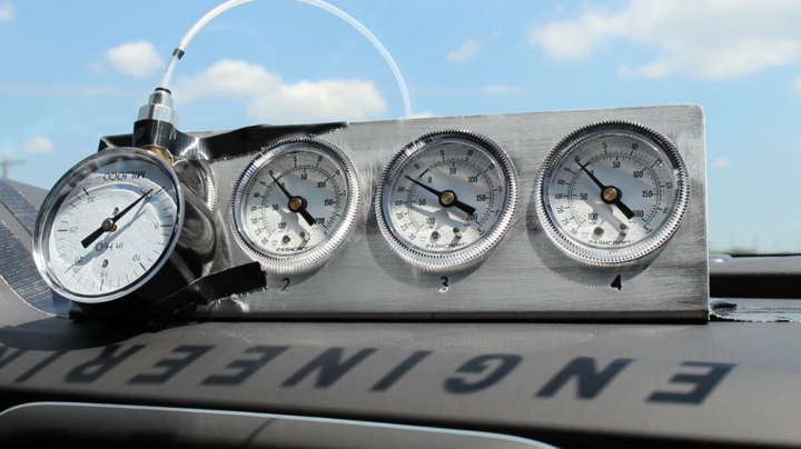
Our custom gauge pod makes it easy to monitor vacuum and pressure from the cabin.
In order to determine exactly how these systems operate, the important thing to understand is when they respectively see pressure or vacuum. By comparing this information to the simultaneous pressure levels within the manifold, we will be able to understand the relationships between boost pressure, throttle position, and respective CCV pressures isolated by system. Knowing this information will allow us to easily deduce the conditions under which each system is actively transferring crankcase pressure (and presumably oil vapor and blow-by) to the induction system, and in which driving scenarios those pressure differentials are occurring most prominently.
Having set up inline pressure sensors to monitor each of the two systems as well as one in the evap system to monitor boost pressure, Steve and I went for a little cruise up I-95 to collect some data. Of course, we needed to emulate all types of driving situations, so we had a little fun maneuvering around some cloverleaf curves, but we also had to control ourselves for a little while and conduct some docile around-town driving. In order to most realistically simulate a real-world situation, we went to Wawa and got some sandwiches.
Reviewing the Notes
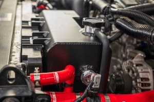
Back at our R&D facility, we reviewed the data and discovered that both systems drew very little vacuum, though the system that routs to the turbo drew marginally more. This seemed like a good place to start, so Steve mounted a catch can for some testing to see if we might catch any blow-by.
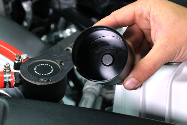
Oil-free since '93
1,000 miles later, the can was free of condensed blow-by and contained nothing more than the faint smell of oil. Of course, I can't be entirely confident in the can as the source of said smell, as a coworker had just driven by in her Subaru.
Puzzled by these results and speculating that the other system, which draws even less vacuum, would produce a similarly negligible amount of blow-by, we sat down, put our thinking caps on, and then I went to Wawa again while Steve began to delve deeper into the diagrams and notes to formulate a plan on how to set up the next round of testing.
No CCV System Left Behind
Approximately one Italian hoagie, one Dr. Pepper, and two Reese's cups later, I returned to the R&D facility to find Steve sitting confidently at his desk, pouring over a 3D diagram of the LTG in our 2.0 and wearing a triumphant smirk on his face. Looked like he had some good news!
Exploring the valve assembly!
After I realized that he was actually on his phone and actively hunting Pokémon beneath his desk, I asked him whether he had made any progress on the Camaro. His response was not one that I had originally expected, but that's why I leave the engineering to him. Having looked through the model, Steve realized that there was a fourth CCV valve in the Camaro 2.0T, integrated into the valve cover and comprising a third unique CCV system. Thank you GM for keeping us on our toes!
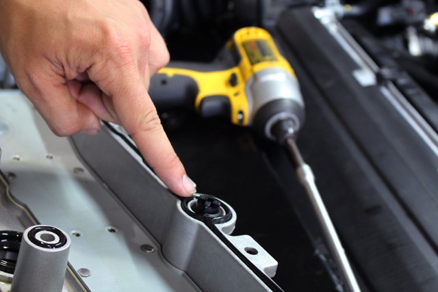
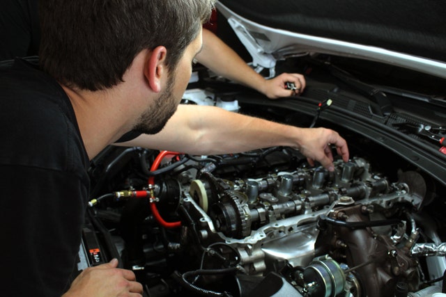
With the valve cover off, you can get a glimpse of the internal PCV valve - who'd a' thunk it?
We made our way back to the car, pulled the valve cover, and sure enough, there it was, built into the cover itself. The system appears to line up with a cavity in the head through which crankcase vapor is presumably redirected to the intake manifold.
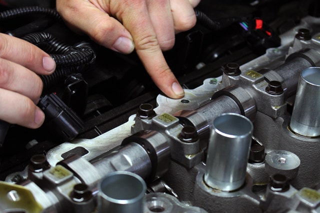
The cavity through which oil vapor is directed. We need this like we need a hole in the head! (ha)
Dealing with an internal, integrated valve presents us with the interesting challenge of determining how - or if - it might be possible to somehow tap into that valve in a way that would allow for a catch can to be integrated inline. This may not be feasible, but we're gonna give it a shot.
PCV Valve Recap
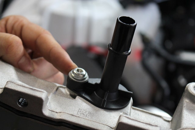
External PCV valve in system number one.
Steve has his work cut out for him, but has already begun examining the system to see if he can find a way around this roadblock. He's extra motivated by the small, but ever-present chance of finding a rare Pokémon hiding in the CCV system.
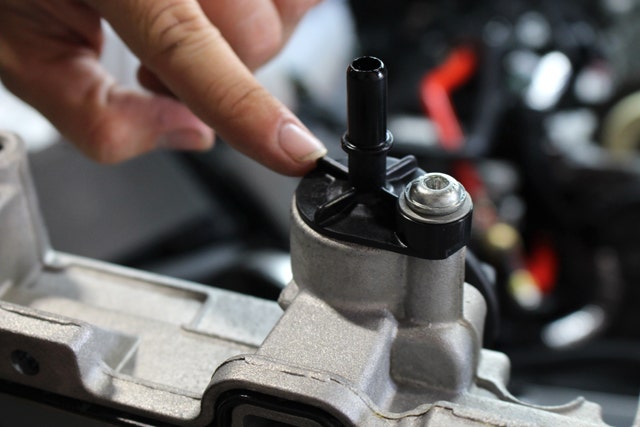
Another External valve on the timing cover; part of system number two.
Next Time"
We hope to have more information for you on this third CCV system coming soon. Otherwise, we will likely be testing the second of the two external systems. Stay tuned for more on this unique project!