Prototype Fabrication and Fitment - Mini Cooper Intake Development, Part 2
In our last post for this project, we went through the stock system and left you with a teaser look at our initial design plans for the filter's heat shield. We now have a functional prototype fabricated, which will soon be ready for testing. Let's go through the interesting process of how we were able to make the heat shield and pipe.
Parts Fabrication
Usually, when it comes to creating the pieces to a heat shield, our process involved measuring twice and cutting once with the use of a band-saw, shears and a bender. It was laborious and time-consuming.
With this project, we took a slightly different approach during the design and prototyping phase of our heat shield R&D. After capturing the dimensions we needed from the vehicle, a prototype design was drawn in 3D modeling software. Once completed, we used our waterjet machine to cut the shapes out of the steel metal sheets.
If you don't know about the waterjet, it is an apparatus for precision cutting using highly pressurized water. Virtually any shape on a flat plane can be made - small or large - limited only by the designer's imagination. Check out an image of the cutting process below. The images on the screen are pieces of the intake box for this Mini Cooper S.
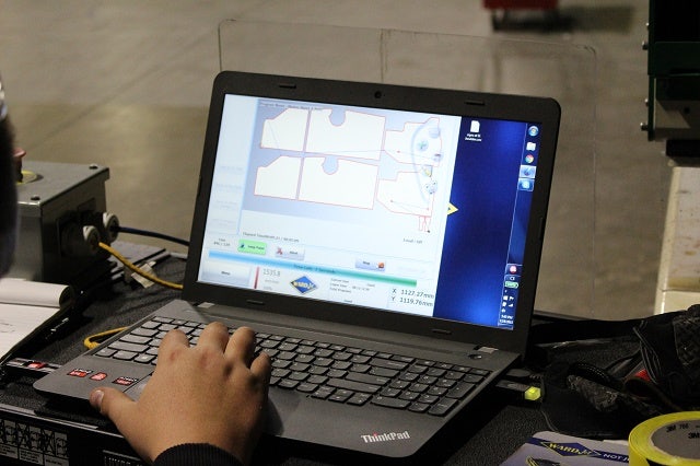
Mini Cooper parts being designed
Now let's check out some of the shield being cut!
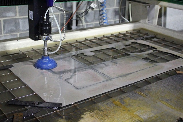
Mini Cooper parts getting cut
Once the procedure is finished, we can take the Mini Cooper air intake piece out one by one to clean them up and grind down the sharp, freshly cut edges.
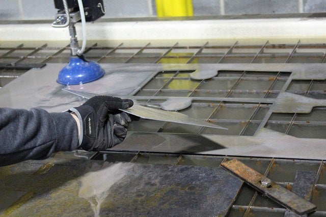
Retrieving Mini Cooper air intake pieces from the waterjet
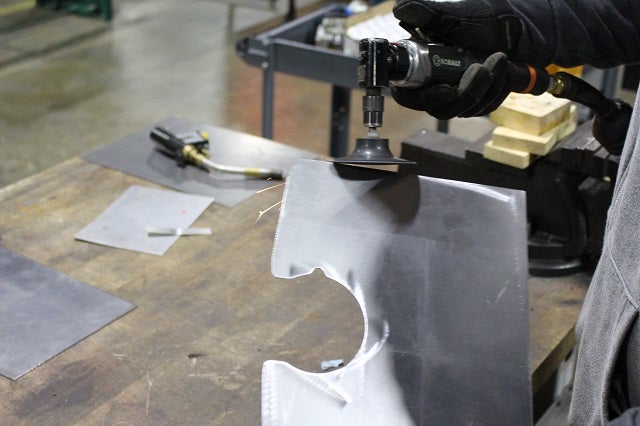
Grinding down Mini Cooper air intake heat shield
These flat metal sheets will be accurately bent to the correct angle. Our fabricator measures the exact angle and bends them on our sheet metal bender.
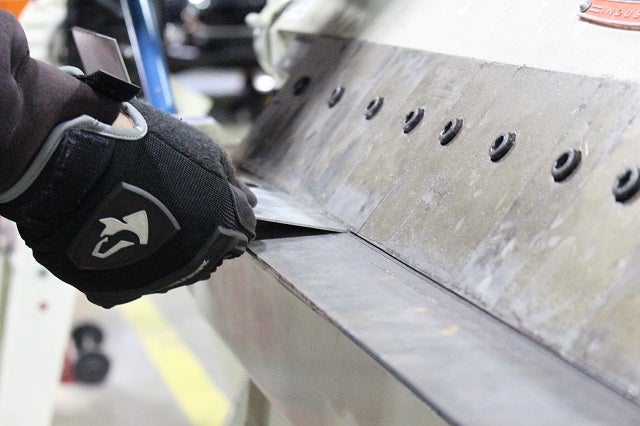
Bending the sides of the shield
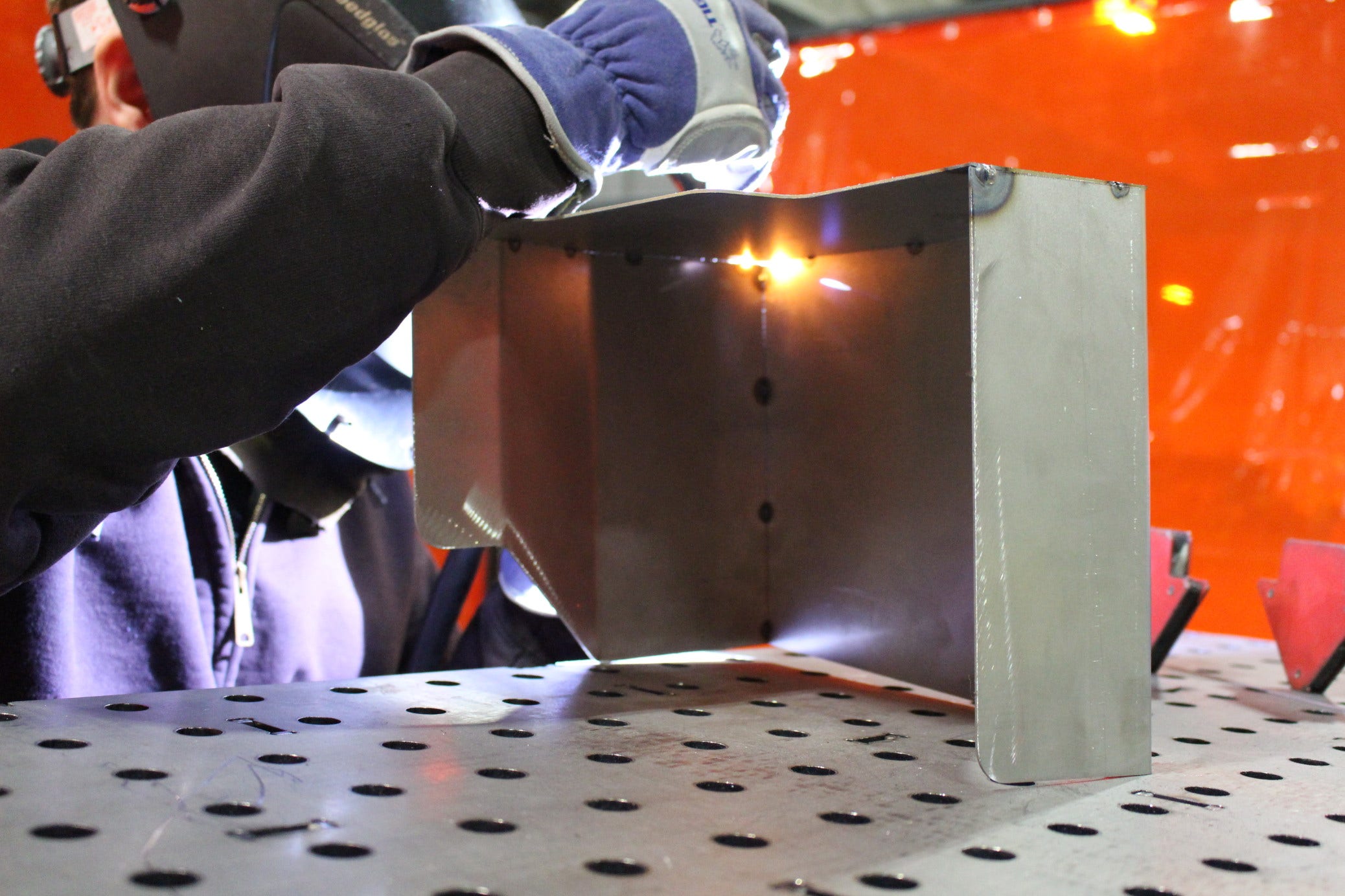
After the pieces are cut and bent, they are assembled and welded in place so the shield can finally start to take shape. This entire method has been a much faster and easier way of box/shield construction - it made our previous methods seem primitive!
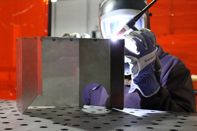
Welding Mini Cooper air intake heat shield
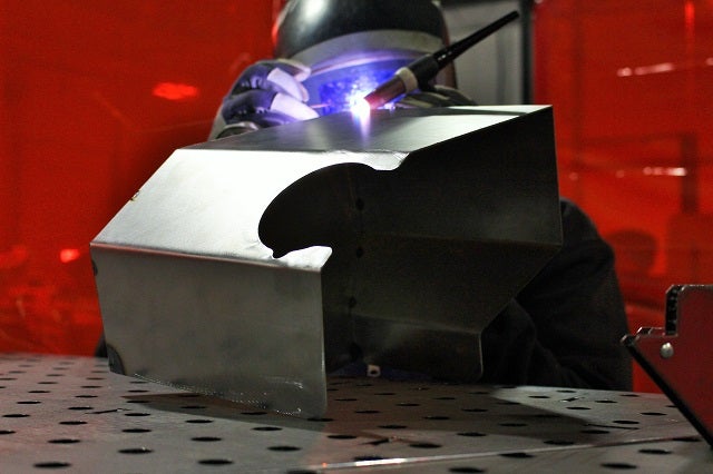
Welding Mini Cooper air intake heat shield
Once all of that is complete, we are now ready to fit the shield into the space.
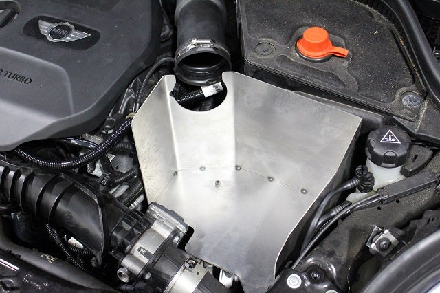
Fitting heat shield into the engine bay
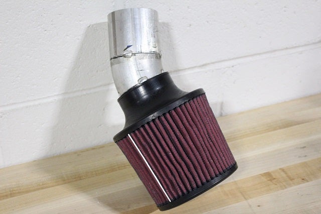
Shot of the prototype pipe
The pipe was fairly simple since it's short, but we used a sizeable filter to support ample airflow. A MAF (mass airflow) adapter will be included with the pipe, so for this prototype, we 3D-printed an adapter. Let's look at how it sits in the box!
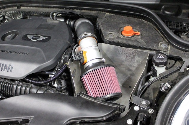
Fitting prototype Mini Cooper parts into the shield
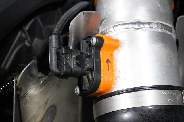
3D Printed MAF adapter
Coming Up
A few more things need to be buttoned up with this prototype before we can begin dyno testing, and our next update will include those dyno results.
The waterjet process was pretty cool, right? We'd love to hear your comments! Thanks for reading and stay tuned for our next update!
-Diamaan