
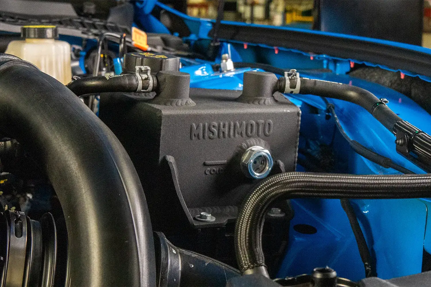
Every owner of a performance vehicle knows the importance of keeping their car running cool, but not everyone knows where to start when it comes to upgrading their cooling system. For owners of the 2024+ Ford Mustang looking to take the next step in performance and reliability for their car’s cooling system, it’s best to start with the basics—the coolant expansion tank.
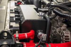
The stock coolant expansion tank on the 2024+ Ford Mustang leaves a lot to be desired. The plastic construction isn’t just an eyesore, it’s not designed to stand the test of time. After repeated heat cycles the plastic yellows and becomes brittle, leading to a higher risk of cracking and coolant leakage. This risk only increases when the vehicle is driven hard, such as fast laps at the track or hard pulls on the dragstrip.